How to Use oled 12c: Examples, Pinouts, and Specs
Introduction
The OLED I2C display is a compact, high-contrast, and energy-efficient display module that uses I2C (Inter-Integrated Circuit) communication for interfacing. It is based on OLED technology, which eliminates the need for a backlight, resulting in deep blacks and excellent visibility even in low-light conditions. These displays are commonly used in projects requiring visual output, such as displaying text, graphics, or sensor data.
Explore Projects Built with oled 12c

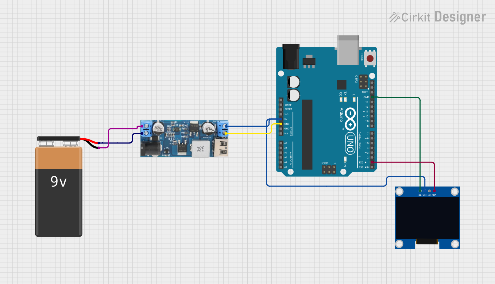
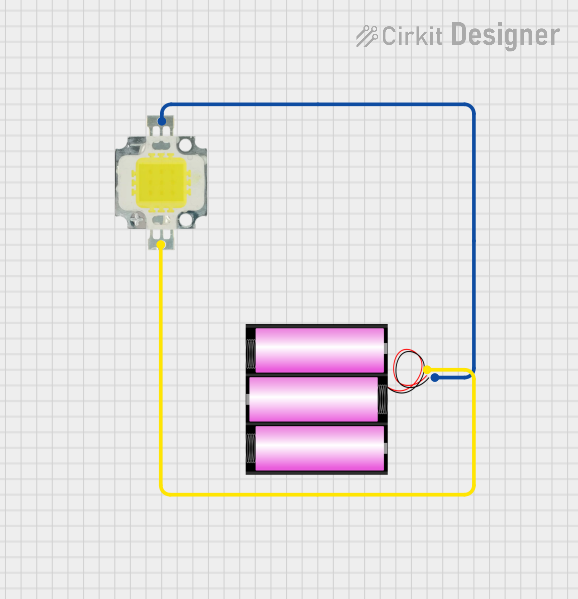
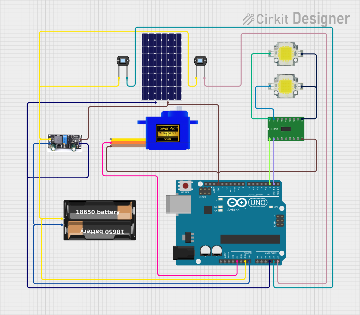
Explore Projects Built with oled 12c
Common Applications and Use Cases
- Wearable devices and smart gadgets
- IoT (Internet of Things) projects
- Sensor data visualization
- Compact user interfaces for embedded systems
- Prototyping with microcontrollers like Arduino, Raspberry Pi, and ESP32
Technical Specifications
- Display Type: OLED (Organic Light Emitting Diode)
- Interface: I2C (Inter-Integrated Circuit)
- Resolution: Commonly 128x64 pixels (varies by model)
- Operating Voltage: 3.3V to 5V
- Current Consumption: ~20mA (varies with brightness)
- Communication Address: Typically 0x3C or 0x3D (configurable on some models)
- Dimensions: Varies by model (e.g., 0.96-inch diagonal for common modules)
Pin Configuration and Descriptions
| Pin | Label | Description |
|---|---|---|
| 1 | GND | Ground (0V reference) |
| 2 | VCC | Power supply (3.3V or 5V) |
| 3 | SCL | I2C Clock Line |
| 4 | SDA | I2C Data Line |
Usage Instructions
How to Use the OLED I2C Display in a Circuit
Connect the Pins:
- Connect the
GNDpin to the ground of your microcontroller. - Connect the
VCCpin to the 3.3V or 5V power supply (depending on your module). - Connect the
SCLpin to the I2C clock pin of your microcontroller (e.g., A5 on Arduino UNO). - Connect the
SDApin to the I2C data pin of your microcontroller (e.g., A4 on Arduino UNO).
- Connect the
Install Required Libraries:
- For Arduino, install the
Adafruit_GFXandAdafruit_SSD1306libraries via the Library Manager in the Arduino IDE.
- For Arduino, install the
Write and Upload Code:
- Use the following example code to display text on the OLED:
#include <Wire.h>
#include <Adafruit_GFX.h>
#include <Adafruit_SSD1306.h>

// Define the OLED display width and height
#define SCREEN_WIDTH 128
#define SCREEN_HEIGHT 64

// Create an instance of the SSD1306 display object
Adafruit_SSD1306 display(SCREEN_WIDTH, SCREEN_HEIGHT, &Wire, -1);

void setup() {
  // Initialize the display
  if (!display.begin(SSD1306_I2C_ADDRESS, 0x3C)) {
    // If the display fails to initialize, halt the program
    Serial.println(F("SSD1306 allocation failed"));
    for (;;);
  }

  // Clear the display buffer
  display.clearDisplay();

  // Set text size and color
  display.setTextSize(1); // Text size multiplier
  display.setTextColor(SSD1306_WHITE);

  // Display a message
  display.setCursor(0, 0); // Set cursor position
  display.println(F("Hello, OLED!"));
  display.display(); // Render the text on the screen
}

void loop() {
  // No actions in the loop for this example
}
Important Considerations and Best Practices
- Power Supply: Ensure the module is powered with the correct voltage (3.3V or 5V).
- I2C Address: Verify the I2C address of your OLED module (commonly 0x3C or 0x3D). Use an I2C scanner sketch if unsure.
- Pull-Up Resistors: Some modules include built-in pull-up resistors for the I2C lines. If not, add external pull-up resistors (4.7kΩ to 10kΩ) to the
SCLandSDAlines. - Library Compatibility: Ensure you are using the correct libraries for your display driver (e.g., SSD1306 or SH1106).
Troubleshooting and FAQs
Common Issues and Solutions
Display Not Turning On:
- Verify the power connections (
GNDandVCC). - Check the I2C address and ensure it matches the one in your code.
- Verify the power connections (
Garbage or No Output on the Screen:
- Ensure the correct libraries (
Adafruit_GFXandAdafruit_SSD1306) are installed. - Double-check the wiring, especially the
SCLandSDAconnections.
- Ensure the correct libraries (
I2C Communication Errors:
- Use an I2C scanner sketch to confirm the module's address.
- Check for loose or incorrect connections on the I2C lines.
Text or Graphics Not Displaying Properly:
- Ensure the display buffer is cleared before rendering new content (
display.clearDisplay()). - Verify the resolution in your code matches the display's resolution.
- Ensure the display buffer is cleared before rendering new content (
FAQs
Q: Can I use the OLED I2C display with a 3.3V microcontroller?
A: Yes, most OLED I2C modules are compatible with both 3.3V and 5V logic levels.Q: How do I change the I2C address of the display?
A: Some modules have solder pads or jumpers to configure the I2C address. Refer to the module's datasheet for details.Q: Can I display images or custom graphics?
A: Yes, you can use theAdafruit_GFXlibrary to draw shapes, bitmaps, and custom graphics.Q: What is the maximum cable length for I2C communication?
A: The maximum length depends on the pull-up resistors and communication speed, but it is typically limited to 1 meter for reliable operation.
By following this documentation, you can effectively integrate and troubleshoot the OLED I2C display in your projects.