How to Use Ultrasonic Distance Measurement Control Board Rangefinder 3 Bit LED Display: Examples, Pinouts, and Specs
Introduction
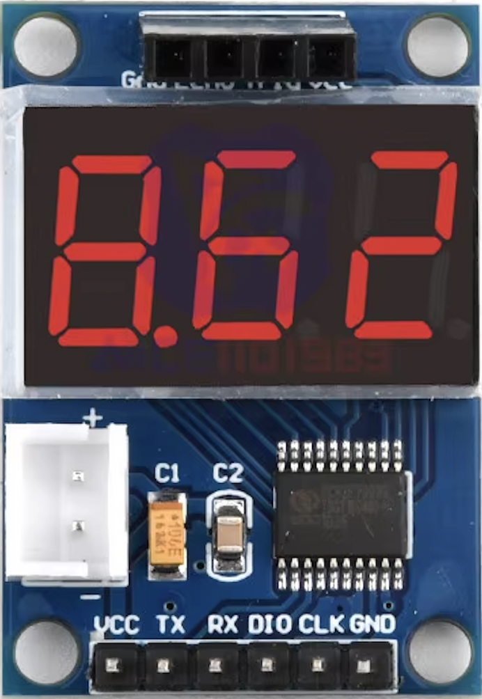
The Ultrasonic Distance Measurement Control Board, manufactured by diymore, is an electronic device designed to measure distances using ultrasonic waves. It integrates an HC-SR04 ultrasonic sensor with an 8-bit microcontroller unit (MCU) and a 3-bit LED display to provide immediate visual feedback. This component is commonly used in robotics, obstacle avoidance systems, parking sensors, and various automation projects where precise distance measurements are required.
Explore Projects Built with Ultrasonic Distance Measurement Control Board Rangefinder 3 Bit LED Display
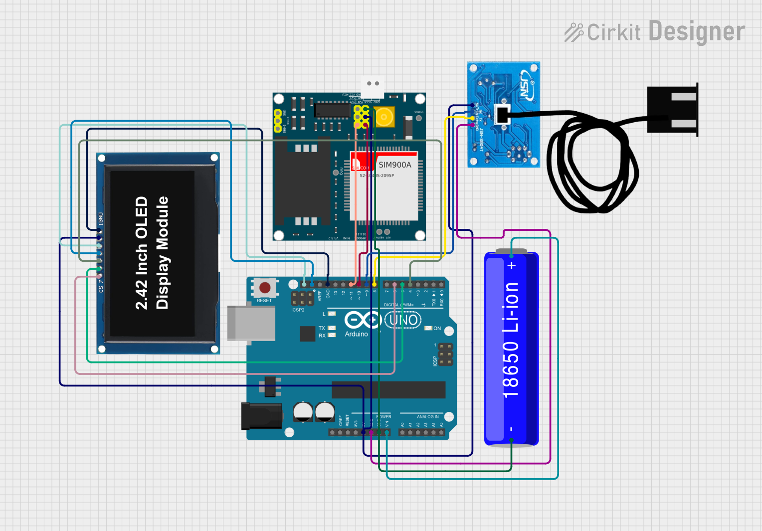
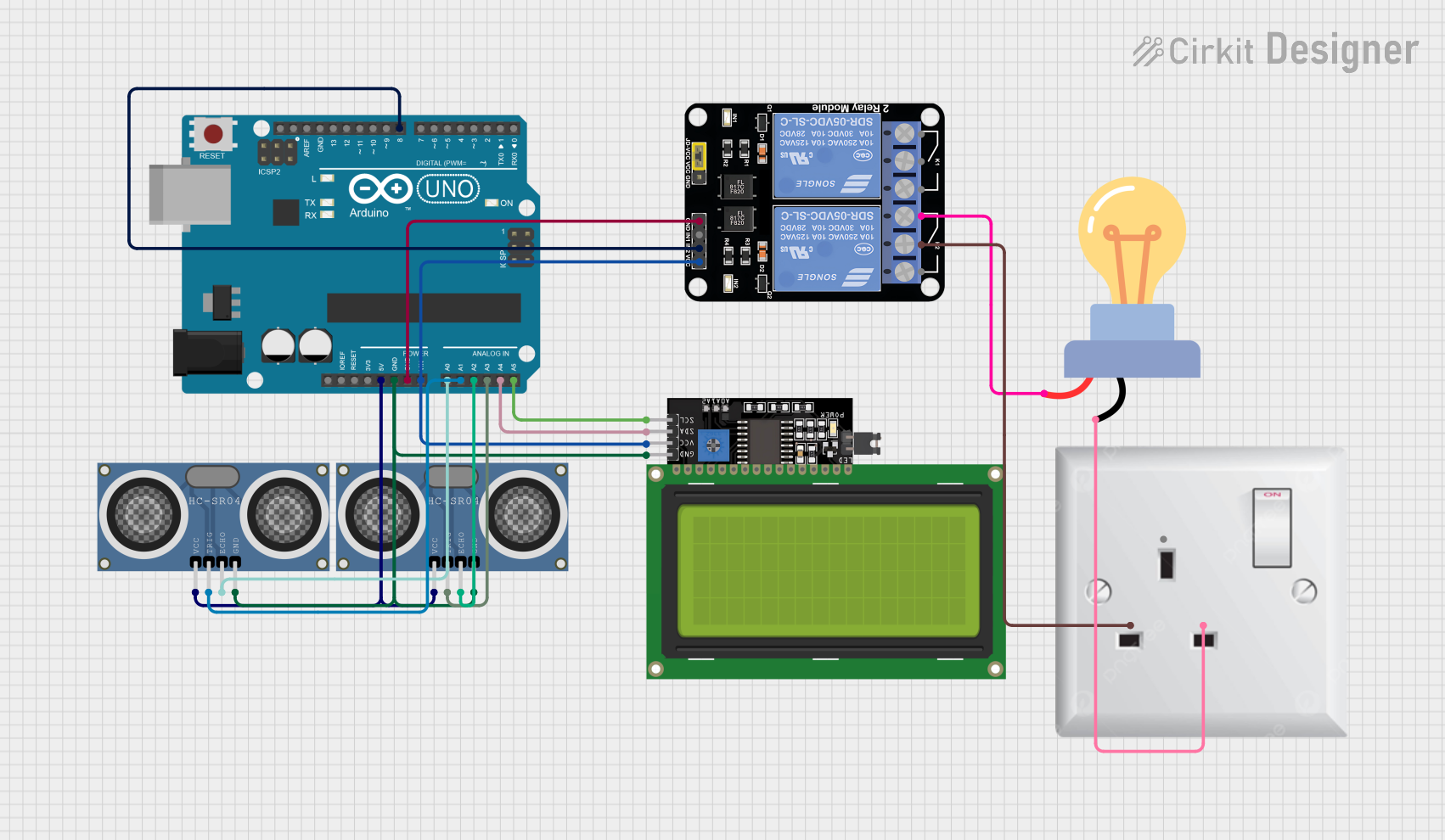
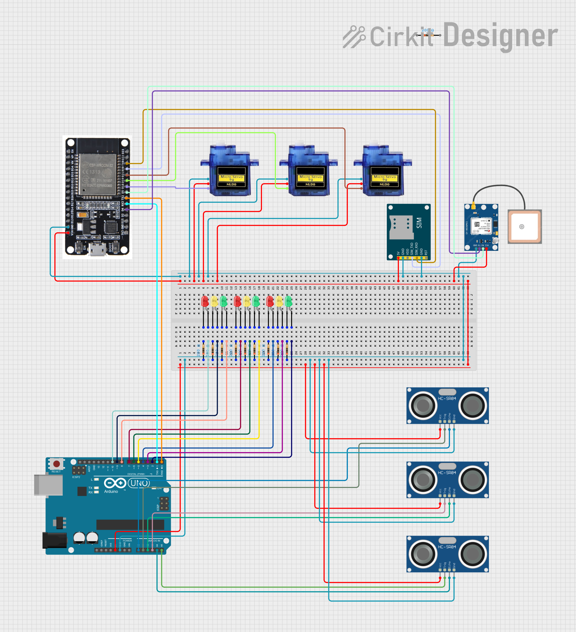
Explore Projects Built with Ultrasonic Distance Measurement Control Board Rangefinder 3 Bit LED Display
Technical Specifications
Key Technical Details
- Operating Voltage: 5V DC
- Current Consumption: 15 mA
- Acoustic Emission Frequency: 40 kHz
- Max Range: 4m
- Min Range: 2cm
- Resolution: 1 cm
- Measurement Angle: 15 degrees
- Display: 3-bit LED for distance indication
Pin Configuration and Descriptions
| Pin Number | Pin Name | Description |
|---|---|---|
| 1 | VCC | Power supply (5V DC) |
| 2 | TRIG | Trigger input (TTL pulse) |
| 3 | ECHO | Echo output (TTL level signal) |
| 4 | GND | Ground |
| 5 | OUT | Digital output (optional, not always used) |
Usage Instructions
Integrating with a Circuit
- Power Supply: Connect the VCC pin to a 5V power source and the GND pin to the ground.
- Triggering the Sensor: Send a 10 µs TTL pulse to the TRIG pin to initiate the measurement.
- Reading the Distance: Monitor the ECHO pin; the duration of the high signal will be proportional to the distance measured.
- Display: The 3-bit LED display will automatically show the distance measurement.
Important Considerations and Best Practices
- Ensure that the power supply does not exceed 5V to avoid damaging the board.
- Avoid placing the sensor in an environment with strong ultrasonic noise to prevent false readings.
- The sensor should not be used to measure soft materials like cloth, which may absorb ultrasonic waves.
- For accurate measurements, keep the sensor perpendicular to the object being measured.
Example Code for Arduino UNO
// Define the pins for the ultrasonic sensor
const int trigPin = 9;
const int echoPin = 10;

void setup() {
  // Initialize serial communication
  Serial.begin(9600);
  // Define sensor pins as input/output
  pinMode(trigPin, OUTPUT);
  pinMode(echoPin, INPUT);
}

void loop() {
  // Clear the trigPin by setting it LOW
  digitalWrite(trigPin, LOW);
  delayMicroseconds(2);

  // Trigger the sensor by setting the trigPin high for 10 microseconds
  digitalWrite(trigPin, HIGH);
  delayMicroseconds(10);
  digitalWrite(trigPin, LOW);

  // Read the echoPin; pulseIn returns the duration (length of the pulse)
  long duration = pulseIn(echoPin, HIGH);

  // Calculate the distance
  int distance = duration * 0.034 / 2; // Speed of sound wave divided by 2 (go and back)

  // Display the distance on the Serial Monitor
  Serial.print("Distance: ");
  Serial.println(distance);

  // Delay between measurements
  delay(500);
}
Troubleshooting and FAQs
Common Issues
- No Readings: Ensure that the VCC and GND connections are secure and that the sensor is powered.
- Inaccurate Readings: Check for obstacles that may interfere with the sensor's line of sight or cause echos.
- LED Display Not Working: Verify that the LED display is correctly soldered and that there are no loose connections.
Solutions and Tips for Troubleshooting
- If the sensor is not functioning, try replacing it to determine if the issue is with the sensor itself.
- For erratic readings, consider adding a filter in your code to average multiple readings.
- Ensure that the trigger pulse to the TRIG pin is exactly 10 µs as required.
FAQs
Q: Can the sensor measure distances beyond 4 meters? A: No, the maximum reliable range for the HC-SR04 is 4 meters.
Q: Is it possible to use this sensor with a 3.3V system? A: The sensor is designed for 5V operation. Using it with 3.3V may result in unreliable performance or no operation at all.
Q: How can I increase the refresh rate of the sensor? A: The refresh rate can be increased by reducing the delay between measurements, but ensure that the sensor has enough time to process the signal and provide a stable reading.