How to Use U-Blox NEO-M10: Examples, Pinouts, and Specs
Introduction
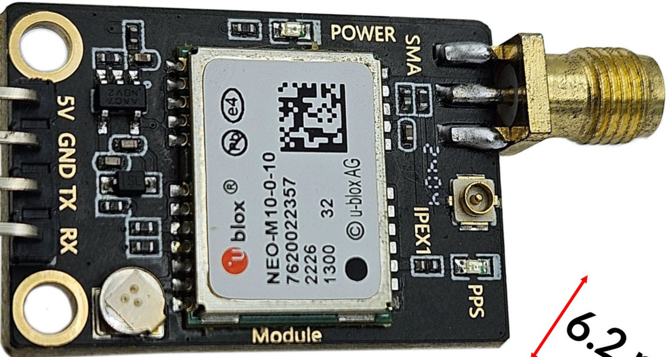
The U-Blox NEO-M10 is a high-performance GPS module designed for accurate positioning and navigation. Manufactured by U-Blox, this module supports multiple Global Navigation Satellite Systems (GNSS), including GPS, Galileo, GLONASS, and BeiDou, ensuring robust and reliable location tracking. It is optimized for low power consumption, making it ideal for battery-powered and portable applications.
Explore Projects Built with U-Blox NEO-M10


Explore Projects Built with U-Blox NEO-M10
Common Applications and Use Cases
- Automotive navigation systems
- Asset tracking and fleet management
- Wearable devices and fitness trackers
- Drones and unmanned aerial vehicles (UAVs)
- IoT devices requiring precise location data
Technical Specifications
The U-Blox NEO-M10 module is packed with advanced features and specifications to meet the demands of modern navigation systems.
Key Technical Details
| Parameter | Specification |
|---|---|
| GNSS Support | GPS, Galileo, GLONASS, BeiDou |
| Frequency Bands | L1 (1575.42 MHz) |
| Positioning Accuracy | 1.5 meters (CEP) |
| Sensitivity | -167 dBm (tracking) |
| Power Supply Voltage | 2.7V to 3.6V |
| Power Consumption | ~21 mA (continuous tracking mode) |
| Operating Temperature | -40°C to +85°C |
| Communication Interfaces | UART, I2C, SPI |
| Dimensions | 12.2 mm x 16.0 mm x 2.4 mm |
Pin Configuration and Descriptions
The U-Blox NEO-M10 module has a standard pinout for easy integration into various systems. Below is the pin configuration:
| Pin Number | Pin Name | Description |
|---|---|---|
| 1 | VCC | Power supply input (2.7V to 3.6V) |
| 2 | GND | Ground |
| 3 | TXD | UART Transmit Data |
| 4 | RXD | UART Receive Data |
| 5 | SDA | I2C Data Line |
| 6 | SCL | I2C Clock Line |
| 7 | SPI_CS | SPI Chip Select |
| 8 | SPI_MISO | SPI Master In Slave Out |
| 9 | SPI_MOSI | SPI Master Out Slave In |
| 10 | SPI_CLK | SPI Clock |
| 11 | RESET_N | Active-low Reset |
| 12 | TIMEPULSE | Time Pulse Output |
Usage Instructions
The U-Blox NEO-M10 module is versatile and can be used in a variety of applications. Below are the steps and considerations for integrating it into a circuit.
How to Use the Component in a Circuit
- Power Supply: Connect the VCC pin to a stable power source (2.7V to 3.6V) and the GND pin to ground.
- Communication Interface: Choose a communication protocol (UART, I2C, or SPI) based on your application:
- For UART, connect the TXD and RXD pins to the corresponding UART pins on your microcontroller.
- For I2C, connect the SDA and SCL pins to the I2C bus.
- For SPI, connect SPI_CS, SPI_MISO, SPI_MOSI, and SPI_CLK to the SPI interface.
- Antenna Connection: Attach an external GNSS antenna to the module for optimal signal reception.
- Reset: Use the RESET_N pin to reset the module if needed.
- Time Pulse: The TIMEPULSE pin can be used for precise timing applications.
Important Considerations and Best Practices
- Antenna Placement: Ensure the GNSS antenna has a clear view of the sky for optimal satellite reception.
- Power Supply: Use a low-noise power supply to avoid interference with GNSS signals.
- Signal Integrity: Keep communication lines short and use proper shielding to minimize noise.
- Firmware Updates: Check for firmware updates from U-Blox to ensure the module operates with the latest features and fixes.
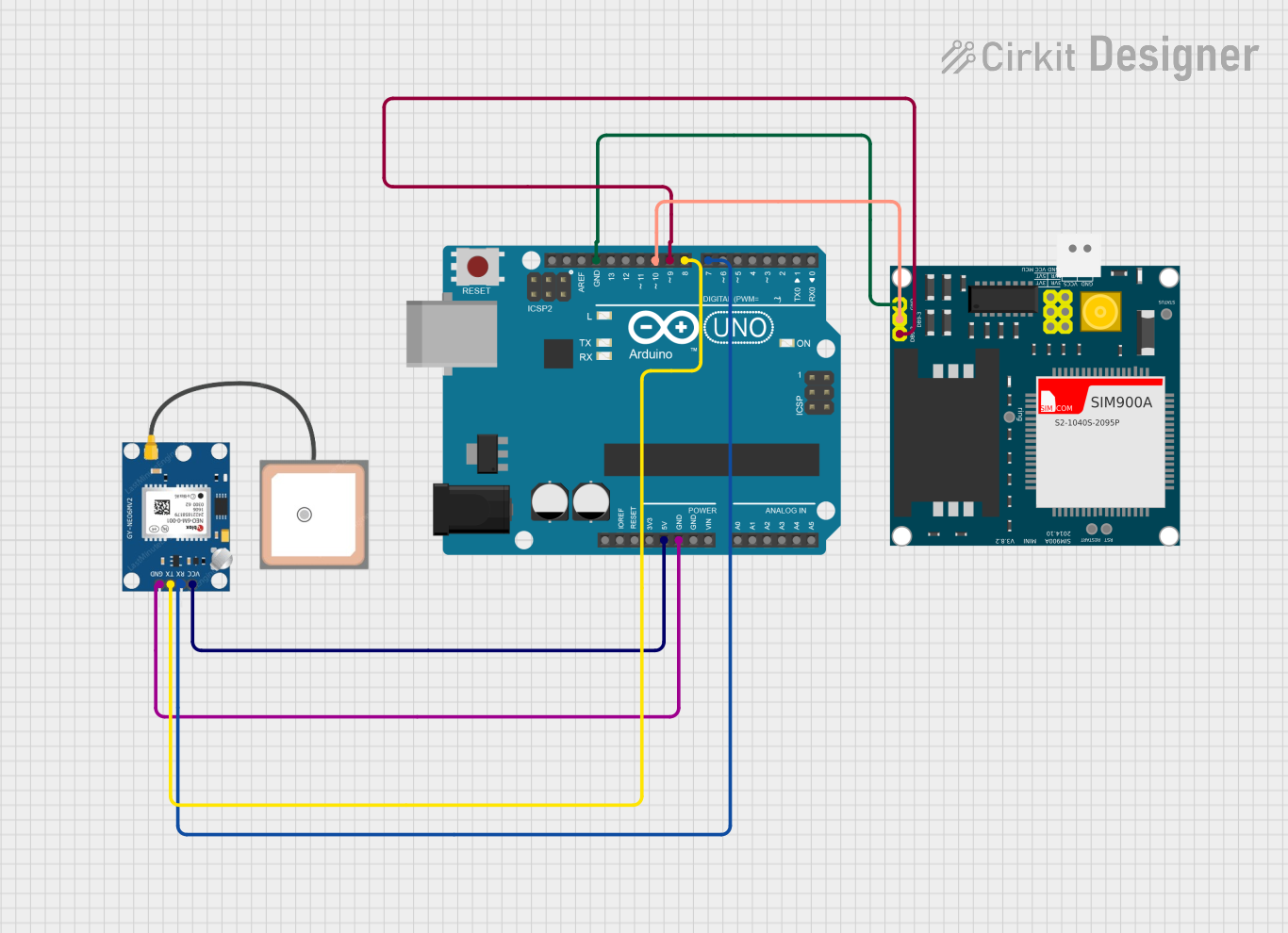
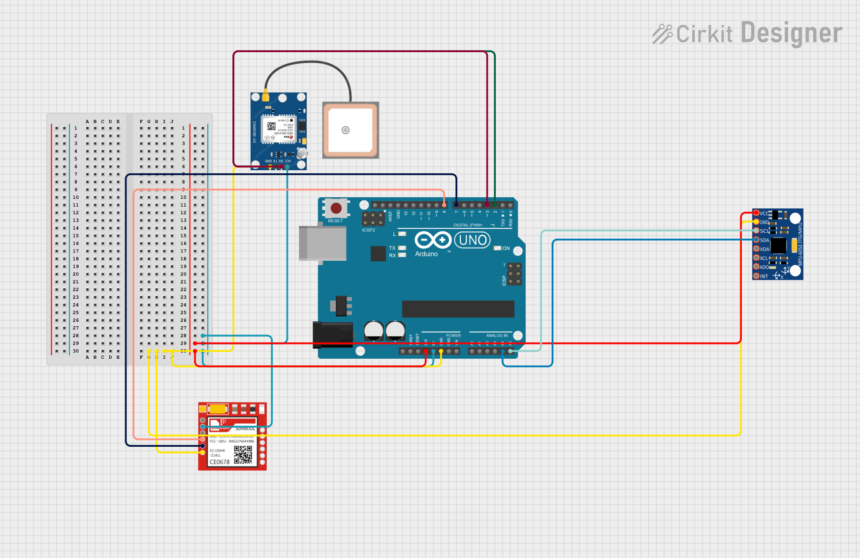
Example: Connecting to an Arduino UNO
The U-Blox NEO-M10 can be easily interfaced with an Arduino UNO using the UART interface. Below is an example code snippet to read GPS data:
#include <SoftwareSerial.h>

// Define RX and TX pins for SoftwareSerial
SoftwareSerial gpsSerial(4, 3); // RX = Pin 4, TX = Pin 3

void setup() {
  Serial.begin(9600);          // Initialize Serial Monitor
  gpsSerial.begin(9600);       // Initialize GPS module communication
  Serial.println("GPS Module Initialized");
}

void loop() {
  // Check if data is available from the GPS module
  while (gpsSerial.available()) {
    char c = gpsSerial.read(); // Read one character from GPS module
    Serial.print(c);           // Print the character to Serial Monitor
  }
}
Notes:
- Connect the GPS module's TXD pin to Arduino's RX pin (Pin 4 in this example).
- Connect the GPS module's RXD pin to Arduino's TX pin (Pin 3 in this example).
- Ensure the module's VCC and GND are properly connected to the Arduino's 3.3V and GND pins.
Troubleshooting and FAQs
Common Issues and Solutions
No GPS Fix:
- Cause: Poor antenna placement or obstructed view of the sky.
- Solution: Place the antenna in an open area with a clear view of the sky.
No Data Output:
- Cause: Incorrect communication interface or baud rate.
- Solution: Verify the selected communication protocol and ensure the baud rate matches the module's default (9600 bps).
Intermittent Signal Loss:
- Cause: Power supply noise or interference.
- Solution: Use a low-noise power supply and ensure proper grounding.
Module Not Responding:
- Cause: Incorrect wiring or damaged module.
- Solution: Double-check all connections and test with a known working module.
FAQs
Q: Can the U-Blox NEO-M10 operate indoors?
A: While the module can operate indoors, signal reception may be weak or unavailable due to obstructions. For best results, use it in open areas.
Q: What is the default baud rate of the module?
A: The default baud rate is 9600 bps.
Q: Does the module support multiple GNSS systems simultaneously?
A: Yes, the U-Blox NEO-M10 can track multiple GNSS systems concurrently for improved accuracy and reliability.
Q: Can I use the module with a 5V microcontroller?
A: The module operates at 3.3V logic levels. Use a level shifter if interfacing with a 5V microcontroller.
This concludes the documentation for the U-Blox NEO-M10 GPS module.