
How to Use Adafruit 4-channel I2C-safe Bi-directional Logic Level Converter: Examples, Pinouts, and Specs
 Design with Adafruit 4-channel I2C-safe Bi-directional Logic Level Converter in Cirkit Designer
Introduction
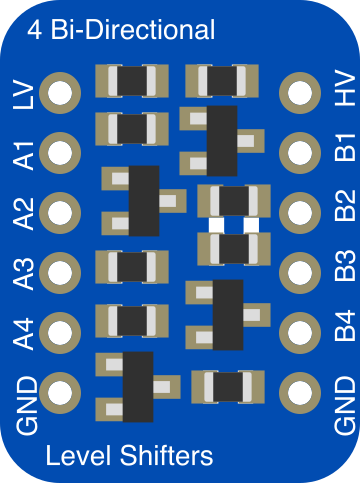
The Adafruit 4-channel I2C-safe Bi-directional Logic Level Converter (Part ID: 757) is a compact and reliable device designed to facilitate communication between devices operating at different voltage levels. It enables seamless bi-directional data transfer, making it ideal for I2C communication and other digital signal applications. This converter is particularly useful when interfacing low-voltage microcontrollers (e.g., 3.3V) with higher-voltage peripherals (e.g., 5V).
Explore Projects Built with Adafruit 4-channel I2C-safe Bi-directional Logic Level Converter
 Open Project in Cirkit Designer
 Open Project in Cirkit Designer
 Open Project in Cirkit DesignerOpen Project in Cirkit Designer
Explore Projects Built with Adafruit 4-channel I2C-safe Bi-directional Logic Level Converter
Open Project in Cirkit DesignerOpen Project in Cirkit DesignerOpen Project in Cirkit DesignerOpen Project in Cirkit DesignerCommon Applications and Use Cases
- Interfacing 3.3V microcontrollers (e.g., Arduino, Raspberry Pi) with 5V sensors or modules.
- Enabling communication between devices with mismatched voltage levels in I2C, UART, or SPI protocols.
- Safeguarding sensitive components from voltage mismatches.
- Prototyping and development of mixed-voltage systems.
Technical Specifications
The Adafruit 4-channel I2C-safe Bi-directional Logic Level Converter is designed with the following key specifications:
| Parameter | Value |
|---|---|
| Operating Voltage (High) | 5V |
| Operating Voltage (Low) | 1.8V to 3.3V |
| Channels | 4 bi-directional channels |
| Communication Protocols | I2C, UART, SPI, GPIO |
| Dimensions | 19mm x 17mm x 2mm |
| Weight | 1g |
Pin Configuration and Descriptions
The logic level converter has the following pin layout:
| Pin Name | Description |
|---|---|
| HV | High-voltage input (e.g., 5V). Connect to the higher voltage power source. |
| LV | Low-voltage input (e.g., 3.3V). Connect to the lower voltage power source. |
| GND | Ground. Connect to the ground of both high- and low-voltage systems. |
| HV1, HV2, HV3, HV4 | High-voltage side of the 4 bi-directional channels. |
| LV1, LV2, LV3, LV4 | Low-voltage side of the 4 bi-directional channels. |
Usage Instructions
How to Use the Component in a Circuit
Power Connections:
- Connect the
HVpin to the high-voltage power source (e.g., 5V). - Connect the
LVpin to the low-voltage power source (e.g., 3.3V). - Connect the
GNDpin to the ground of both voltage systems.
- Connect the
Signal Connections:
- Connect the high-voltage signal lines to the
HVxpins. - Connect the corresponding low-voltage signal lines to the
LVxpins. - Ensure that each channel (e.g., HV1 ↔ LV1) is used for a single signal line.
- Connect the high-voltage signal lines to the
I2C Communication:
- For I2C applications, connect the
SCLandSDAlines of the high-voltage device to twoHVxpins. - Similarly, connect the
SCLandSDAlines of the low-voltage device to the correspondingLVxpins.
- For I2C applications, connect the
Important Considerations and Best Practices
- Ensure that the
HVandLVpower sources are stable and within the specified voltage ranges. - Do not exceed the maximum voltage ratings to avoid damaging the converter or connected devices.
- Use pull-up resistors on the I2C lines if required. The converter is I2C-safe and works with or without external pull-ups.
- Keep the wiring as short as possible to minimize signal degradation, especially for high-speed communication.
Example: Connecting to an Arduino UNO
Below is an example of using the logic level converter to interface a 3.3V sensor with a 5V Arduino UNO via I2C:
Circuit Connections
- Connect the Arduino's
5Vpin to theHVpin of the converter. - Connect the Arduino's
GNDpin to theGNDpin of the converter. - Connect the sensor's
3.3Vpin to theLVpin of the converter. - Connect the sensor's
GNDpin to theGNDpin of the converter. - Connect the Arduino's
SCLandSDApins toHV1andHV2, respectively. - Connect the sensor's
SCLandSDApins toLV1andLV2, respectively.
Arduino Code Example
#include <Wire.h> // Include the Wire library for I2C communication

void setup() {
  Wire.begin(); // Initialize I2C communication
  Serial.begin(9600); // Start serial communication for debugging
  Serial.println("I2C Logic Level Converter Example");
}

void loop() {
  // Example: Request data from a sensor at I2C address 0x40
  Wire.beginTransmission(0x40); // Start communication with the sensor
  Wire.write(0x00); // Send a command or register address
  Wire.endTransmission(); // End the transmission

  Wire.requestFrom(0x40, 2); // Request 2 bytes of data from the sensor
  if (Wire.available() == 2) {
    int data = Wire.read() << 8 | Wire.read(); // Read and combine the 2 bytes
    Serial.print("Sensor Data: ");
    Serial.println(data); // Print the received data
  }

  delay(1000); // Wait for 1 second before the next request
}
Troubleshooting and FAQs
Common Issues and Solutions
No Communication Between Devices:
- Verify that the
HVandLVpower sources are correctly connected and within the specified voltage ranges. - Check the wiring of the signal lines to ensure proper connections between
HVxandLVx.
- Verify that the
Signal Degradation or Noise:
- Use shorter wires to reduce signal interference.
- Add pull-up resistors to the I2C lines if necessary.
Overheating or Damage:
- Ensure that the voltage levels do not exceed the specified limits.
- Double-check the ground connections between all devices.
FAQs
Q: Can this converter be used for SPI communication?
A: Yes, the converter supports SPI communication. However, ensure that the SPI clock speed is within the tolerable range for the connected devices.
Q: Do I need external pull-up resistors for I2C?
A: The converter is I2C-safe and works with or without external pull-up resistors. However, adding pull-ups may improve signal integrity in some cases.
Q: Can I use this converter for analog signals?
A: No, this converter is designed for digital signals only. It is not suitable for analog signal conversion.
Q: What is the maximum data rate supported?
A: The converter supports data rates up to 400kHz for I2C communication. For other protocols, ensure compatibility with the connected devices.