How to Use Joystick module : Examples, Pinouts, and Specs
Introduction
The joystick module is a versatile input device that translates physical movement into analog signals. It typically consists of two potentiometers (one for the X-axis and one for the Y-axis) that provide variable resistance based on the position of the stick. A push-button may also be included, activated by pressing down on the joystick. This module is widely used in robotics, gaming controls, and various DIY electronics projects for directional input and control.
Explore Projects Built with Joystick module


Explore Projects Built with Joystick module
Common Applications and Use Cases
- Robotics: controlling the movement of robotic arms or vehicles.
- Gaming: DIY game controllers or arcade machines.
- Simulations: flight or driving simulators.
- Educational projects: teaching principles of analog input and control systems.
Technical Specifications
Key Technical Details
- Voltage: 3.3V to 5V
- Current: 10mA (typical)
- Dimensions: Varies by model, typically around 4cm x 2.5cm x 3.2cm
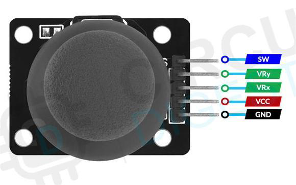
Pin Configuration and Descriptions
| Pin | Description |
|---|---|
| GND | Ground |
| +5V | Power supply (3.3-5V) |
| VRx | X-axis analog output |
| VRy | Y-axis analog output |
| SW | Push-button switch |
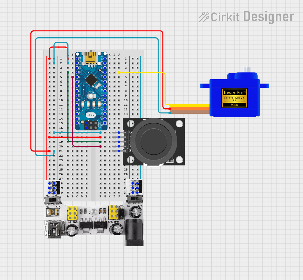
Usage Instructions
How to Use the Component in a Circuit
- Connect the GND pin to the ground on your microcontroller.
- Connect the +5V pin to a 3.3V or 5V power supply from your microcontroller.
- Connect the VRx pin to an analog input pin for X-axis readings.
- Connect the VRy pin to another analog input pin for Y-axis readings.
- If the joystick has a SW pin, connect it to a digital pin for the button press feature.
Important Considerations and Best Practices
- Ensure that the power supply matches the voltage requirements of the joystick module.
- Use pull-up or pull-down resistors with the SW button if the module does not have built-in resistors.
- Calibrate the joystick's center position in your code to account for any offset in the resting position.
- Implement software debouncing for the button to prevent false triggers from electrical noise.
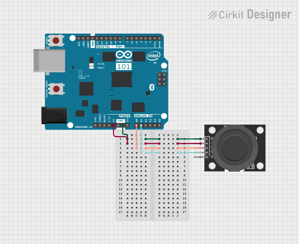
Example Code for Arduino UNO
// Define joystick connections with Arduino
const int xAxisPin = A0; // VRx connected to analog pin A0
const int yAxisPin = A1; // VRy connected to analog pin A1
const int buttonPin = 2; // SW connected to digital pin 2

void setup() {
  pinMode(buttonPin, INPUT_PULLUP); // Set button pin as input with internal pull-up
  Serial.begin(9600); // Start serial communication at 9600 baud
}

void loop() {
  int xPosition = analogRead(xAxisPin); // Read the position of the joystick on the X-axis
  int yPosition = analogRead(yAxisPin); // Read the position of the joystick on the Y-axis
  bool buttonState = !digitalRead(buttonPin); // Read the button state (active low)

  // Print the X, Y positions and button state to the serial monitor
  Serial.print("X: ");
  Serial.print(xPosition);
  Serial.print(" | Y: ");
  Serial.print(yPosition);
  Serial.print(" | Button: ");
  Serial.println(buttonState ? "Pressed" : "Released");

  delay(100); // Delay for stability
}
Troubleshooting and FAQs
Common Issues Users Might Face
- Inaccurate Readings: If the joystick provides inconsistent readings, check for loose connections or damaged potentiometers.
- Button Not Responding: Ensure the button is properly connected and the internal pull-up resistor is enabled in the code.
- Drifting: If the joystick drifts from the center, implement calibration in your code to define a stable center position.
Solutions and Tips for Troubleshooting
- Double-check all connections and ensure they are secure.
- Use the
analogReference()function in Arduino if you are using a reference voltage other than the default 5V. - Add a small delay in the loop to prevent reading noise and to debounce the button.
FAQs
Q: Can I use the joystick module with a 3.3V system? A: Yes, the joystick module can typically operate at 3.3V, but check the specific model's datasheet.
Q: How do I interpret the analog values from the joystick? A: The values range from 0 to 1023 for Arduino, with ~512 being the center position.
Q: Is it possible to use the joystick without an Arduino? A: Yes, the joystick can be used with any microcontroller that has analog inputs.
Q: How can I increase the precision of the joystick readings?
A: Use the analogReadResolution() function if your microcontroller supports it, or add external ADC with higher resolution.