Cirkit Designer Logo
Cirkit Designer
Your all-in-one circuit design IDE
Home / 
Component Documentation

How to Use esp32: Examples, Pinouts, and Specs

Image of esp32
Cirkit Designer LogoDesign with esp32 in Cirkit Designer

Introduction

The ESP32 is a low-cost, low-power system on a chip (SoC) developed by Espressif Systems. It features integrated Wi-Fi and Bluetooth capabilities, making it an ideal choice for Internet of Things (IoT) applications, smart devices, and embedded systems. The ESP32 is highly versatile, offering dual-core processing, a wide range of GPIO pins, and support for various communication protocols.

Explore Projects Built with esp32

Use Cirkit Designer to design, explore, and prototype these projects online. Some projects support real-time simulation. Click "Open Project" to start designing instantly!
ESP32-Controlled OLED Display and Servo with DotStar LED Strip and Audio Output
Image of Arena 2: A project utilizing esp32 in a practical application
This circuit features an ESP32 microcontroller driving a variety of components. It controls an OLED display for visual output, a DotStar LED strip for lighting effects, a PAM8403 audio amplifier connected to a speaker for sound output, and a PCA9685 PWM Servo Breakout to manage a servo motor. The ESP32 also interfaces with a piezo speaker for additional sound generation, and the circuit is powered by a 18650 Li-ion battery setup with a TP4056 charging module. The ESP32's embedded code handles the display animation on the OLED.
Cirkit Designer LogoOpen Project in Cirkit Designer
ESP32-Based Sensor Monitoring System with OLED Display and E-Stop
Image of MVP_design: A project utilizing esp32 in a practical application
This circuit features an ESP32 microcontroller that interfaces with a variety of sensors and output devices. It is powered by a Lipo battery through a buck converter, ensuring a stable voltage supply. The ESP32 collects data from a DHT11 temperature and humidity sensor and a vibration sensor, controls a buzzer, and displays information on an OLED screen. An emergency stop (E Stop) is connected for safety purposes, allowing the system to be quickly deactivated.
Cirkit Designer LogoOpen Project in Cirkit Designer
ESP32-Based Environmental Monitoring System with Motion Detection
Image of pro: A project utilizing esp32 in a practical application
This circuit features an ESP32 microcontroller on a baseboard that interfaces with a PIR sensor for motion detection, a DHT22 sensor for measuring temperature and humidity, and a BH1750 sensor for detecting ambient light levels. The ESP32 is configured to communicate with the BH1750 using I2C protocol, with GPIO22 and GPIO21 serving as the SCL and SDA lines, respectively. Power is supplied to the sensors from the ESP32's voltage output pins, and sensor outputs are connected to designated GPIO pins for data acquisition.
Cirkit Designer LogoOpen Project in Cirkit Designer
ESP32-Based Smart Weather Station with Wi-Fi Connectivity
Image of flowchart 3D: A project utilizing esp32 in a practical application
This circuit features an ESP32 microcontroller interfacing with various sensors and modules, including a DHT22 temperature and humidity sensor, an ESP32 CAM for image capture, an I2C LCD screen for display, a load cell with an HX711 interface for weight measurement, and a buzzer for audio alerts. The ESP32 handles data acquisition, processing, and communication with these peripherals to create a multi-functional monitoring and alert system.
Cirkit Designer LogoOpen Project in Cirkit Designer

Explore Projects Built with esp32

Use Cirkit Designer to design, explore, and prototype these projects online. Some projects support real-time simulation. Click "Open Project" to start designing instantly!
Image of Arena 2: A project utilizing esp32 in a practical application
ESP32-Controlled OLED Display and Servo with DotStar LED Strip and Audio Output
This circuit features an ESP32 microcontroller driving a variety of components. It controls an OLED display for visual output, a DotStar LED strip for lighting effects, a PAM8403 audio amplifier connected to a speaker for sound output, and a PCA9685 PWM Servo Breakout to manage a servo motor. The ESP32 also interfaces with a piezo speaker for additional sound generation, and the circuit is powered by a 18650 Li-ion battery setup with a TP4056 charging module. The ESP32's embedded code handles the display animation on the OLED.
Cirkit Designer LogoOpen Project in Cirkit Designer
Image of MVP_design: A project utilizing esp32 in a practical application
ESP32-Based Sensor Monitoring System with OLED Display and E-Stop
This circuit features an ESP32 microcontroller that interfaces with a variety of sensors and output devices. It is powered by a Lipo battery through a buck converter, ensuring a stable voltage supply. The ESP32 collects data from a DHT11 temperature and humidity sensor and a vibration sensor, controls a buzzer, and displays information on an OLED screen. An emergency stop (E Stop) is connected for safety purposes, allowing the system to be quickly deactivated.
Cirkit Designer LogoOpen Project in Cirkit Designer
Image of pro: A project utilizing esp32 in a practical application
ESP32-Based Environmental Monitoring System with Motion Detection
This circuit features an ESP32 microcontroller on a baseboard that interfaces with a PIR sensor for motion detection, a DHT22 sensor for measuring temperature and humidity, and a BH1750 sensor for detecting ambient light levels. The ESP32 is configured to communicate with the BH1750 using I2C protocol, with GPIO22 and GPIO21 serving as the SCL and SDA lines, respectively. Power is supplied to the sensors from the ESP32's voltage output pins, and sensor outputs are connected to designated GPIO pins for data acquisition.
Cirkit Designer LogoOpen Project in Cirkit Designer
Image of flowchart 3D: A project utilizing esp32 in a practical application
ESP32-Based Smart Weather Station with Wi-Fi Connectivity
This circuit features an ESP32 microcontroller interfacing with various sensors and modules, including a DHT22 temperature and humidity sensor, an ESP32 CAM for image capture, an I2C LCD screen for display, a load cell with an HX711 interface for weight measurement, and a buzzer for audio alerts. The ESP32 handles data acquisition, processing, and communication with these peripherals to create a multi-functional monitoring and alert system.
Cirkit Designer LogoOpen Project in Cirkit Designer

Common Applications and Use Cases

  • IoT devices (e.g., smart home systems, sensors, and actuators)
  • Wearable technology
  • Wireless communication hubs
  • Robotics and automation
  • Data logging and remote monitoring
  • Prototyping and educational projects

Technical Specifications

The ESP32 is available in various module configurations, but the following specifications are common across most variants:

Key Technical Details

  • Processor: Dual-core Xtensa® 32-bit LX6 microprocessor
  • Clock Speed: Up to 240 MHz
  • RAM: 520 KB SRAM
  • Flash Memory: Typically 4 MB (varies by module)
  • Wi-Fi: 802.11 b/g/n (2.4 GHz)
  • Bluetooth: v4.2 BR/EDR and BLE
  • Operating Voltage: 3.0V to 3.6V
  • GPIO Pins: Up to 34 (multiplexed with other functions)
  • ADC: 12-bit, up to 18 channels
  • DAC: 2 channels (8-bit resolution)
  • PWM: Supported on most GPIO pins
  • Communication Protocols: SPI, I2C, UART, I2S, CAN, Ethernet MAC
  • Power Consumption: Ultra-low power modes available (as low as 5 µA in deep sleep)

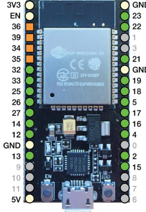
Pin Configuration and Descriptions

The ESP32 has a flexible pinout, but the following table describes the most commonly used pins:

Pin Name Function Description
GPIO0 Input/Output, Boot Mode Select Used for boot mode selection during startup. Can also be used as a GPIO pin.
GPIO2 Input/Output, ADC, PWM General-purpose pin with ADC and PWM capabilities.
GPIO12 Input/Output, ADC, Touch Sensor Can function as an ADC input or capacitive touch sensor.
GPIO13 Input/Output, ADC, Touch Sensor Similar to GPIO12, supports ADC and touch sensing.
GPIO15 Input/Output, ADC, PWM General-purpose pin with ADC and PWM capabilities.
GPIO16 Input/Output General-purpose pin.
GPIO17 Input/Output General-purpose pin.
EN Enable Active-high pin to enable or reset the chip.
3V3 Power Supply Provides 3.3V power to the ESP32.
GND Ground Ground connection.

Note: The exact pinout may vary depending on the ESP32 module (e.g., ESP32-WROOM-32, ESP32-WROVER).

Usage Instructions

How to Use the ESP32 in a Circuit

  1. Powering the ESP32:
    • Connect the 3V3 pin to a 3.3V power source.
    • Ensure the GND pin is connected to the ground of the circuit.
  2. Programming the ESP32:
    • Use a USB-to-serial adapter or a development board with a built-in USB interface.
    • Install the ESP32 board package in the Arduino IDE or use the Espressif IDF (IoT Development Framework).
  3. Connecting Peripherals:
    • Use GPIO pins for digital input/output.
    • Connect sensors to ADC pins for analog input.
    • Use I2C, SPI, or UART for communication with external devices.

Important Considerations and Best Practices

  • Voltage Levels: The ESP32 operates at 3.3V logic levels. Avoid connecting 5V signals directly to its GPIO pins.
  • Boot Mode: Ensure GPIO0 is pulled low during startup to enter programming mode.
  • Power Supply: Use a stable power source to avoid unexpected resets or malfunctions.
  • Deep Sleep: Utilize the deep sleep mode for battery-powered applications to conserve energy.

Example Code for Arduino IDE

The following example demonstrates how to blink an LED connected to GPIO2:

// Define the GPIO pin for the LED
#define LED_PIN 2

void setup() {
  // Set the LED pin as an output
  pinMode(LED_PIN, OUTPUT);
}

void loop() {
  // Turn the LED on
  digitalWrite(LED_PIN, HIGH);
  delay(1000); // Wait for 1 second

  // Turn the LED off
  digitalWrite(LED_PIN, LOW);
  delay(1000); // Wait for 1 second
}

Troubleshooting and FAQs

Common Issues and Solutions

  1. ESP32 Not Detected by the Computer:

    • Ensure the correct USB driver is installed (e.g., CP210x or CH340 driver).
    • Check the USB cable for damage or try a different cable.
  2. Upload Fails with "Failed to Connect" Error:

    • Hold the "BOOT" button on the ESP32 board while uploading the code.
    • Verify that GPIO0 is pulled low during programming.
  3. Random Resets or Instability:

    • Check the power supply for sufficient current (at least 500 mA recommended).
    • Add a capacitor (e.g., 10 µF) near the 3V3 pin to stabilize the power.
  4. Wi-Fi Connection Issues:

    • Ensure the correct SSID and password are used in the code.
    • Check for interference or weak signal strength.

FAQs

  • Q: Can the ESP32 operate on 5V?

    • A: No, the ESP32 operates at 3.3V. Use a voltage regulator or level shifter for 5V systems.
  • Q: How many devices can connect to the ESP32 via Bluetooth?

    • A: The ESP32 supports up to 7 devices in Bluetooth Classic mode and multiple devices in BLE mode.
  • Q: Can the ESP32 be used without Wi-Fi or Bluetooth?

    • A: Yes, the ESP32 can function as a standalone microcontroller without using its wireless features.
  • Q: What is the maximum range of the ESP32's Wi-Fi?

    • A: The range depends on environmental factors but typically extends up to 100 meters in open space.

By following this documentation, users can effectively integrate the ESP32 into their projects and troubleshoot common issues.