How to Use TP4056: Examples, Pinouts, and Specs

 Design with TP4056 in Cirkit Designer
Introduction
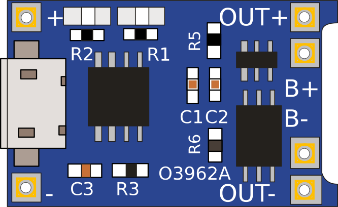
The TP4056 is a complete constant-current/constant-voltage linear charger for single-cell lithium-ion and lithium polymer batteries. Its SOP package and low external component count make the TP4056 ideally suited for portable applications. Furthermore, the TP4056 can work within USB and wall adapter power specifications. Common applications include portable devices, like DIY projects, microcontroller boards, and standalone battery chargers.
Explore Projects Built with TP4056

 Open Project in Cirkit Designer
 Open Project in Cirkit Designer
 Open Project in Cirkit Designer
 Open Project in Cirkit Designer
Explore Projects Built with TP4056

 Open Project in Cirkit Designer
 Open Project in Cirkit Designer
 Open Project in Cirkit Designer
 Open Project in Cirkit Designer
Technical Specifications
Key Technical Details
- Charge Voltage: 4.2V ±1%
- Charge Current: Programmable from 1mA to 1000mA
- Input Voltage Range: 4.5V to 5.5V
- Operating Temperature: -10°C to +85°C
- Battery Overcharge Protection Voltage: 4.2V ±1%
- Battery Discharge Protection Voltage: 2.4V ±1%
- Max Charging Current: 1A (adjustable)
Pin Configuration and Descriptions
| Pin Number | Pin Name | Description |
|---|---|---|
| 1 | BAT | Battery positive connection |
| 2 | GND | Ground connection |
| 3 | VCC | Input power supply (4.5V-5.5V) |
| 4 | TEMP | Temperature sense (optional) |
| 5 | PROG | Charge current programming pin |
| 6 | STAT | Charge status output pin |
Usage Instructions
Connecting the TP4056 to a Circuit
- Power Supply: Connect a 5V power supply to the VCC and GND pins. Ensure that the power supply can deliver the necessary current for charging.
- Battery Connection: Attach the positive terminal of the lithium battery to the BAT pin and the negative terminal to the GND pin.
- Setting Charge Current: The default charge current is set to 1A. To adjust the charging current, place a resistor between the PROG pin and GND. The charge current is set by the formula:
Icharge = 1200 / Rprog (mA), where Rprog is in ohms. - Charge Status: The STAT pin can be used to indicate the charging status. When charging, the STAT pin will be low. Once charging is complete, it will go high.
Important Considerations and Best Practices
- Do not exceed the recommended input voltage range (4.5V to 5.5V).
- Ensure the battery's charge and discharge ratings are compatible with the TP4056.
- Avoid placing the module in high-temperature environments to prevent overheating.
- Use a heat sink if charging at currents higher than 500mA.
- Always double-check wiring before powering up to prevent damage to the module or battery.
Troubleshooting and FAQs
Common Issues
- LED Indicator Not Lighting Up: Ensure the power supply is correctly connected and within the specified voltage range.
- Battery Not Charging: Check the battery connections and ensure the battery is not faulty.
- Module Overheating: Reduce the charging current or attach a heat sink to the TP4056.
Solutions and Tips
- Adjusting Charge Current: Use a multimeter to measure the current and adjust the PROG resistor accordingly.
- Improving Heat Dissipation: Attach the module to a metallic surface or use a heat sink.
- Ensuring Battery Health: Do not leave the battery connected to the charger after charging is complete to avoid over-discharge.
FAQs
Q: Can I charge multiple batteries with one TP4056 module? A: No, the TP4056 is designed for single-cell lithium-ion or lithium polymer batteries.
Q: What should I do if the TP4056 is getting too hot during charging? A: Ensure that the charging current is not set too high for your application. Consider adding a heat sink or reducing the charge current.
Q: Can the TP4056 be used without the temperature sensing pin? A: Yes, the TEMP pin is optional. If not used, it should be left unconnected.
Example Code for Arduino UNO
The following example demonstrates how to read the charge status from the TP4056 using an Arduino UNO.
// Define the STAT pin connected to the Arduino
const int STATpin = 7;

void setup() {
  pinMode(STATpin, INPUT);
  Serial.begin(9600);
}

void loop() {
  // Read the charging status from the STAT pin
  int chargeStatus = digitalRead(STATpin);

  // Check if the battery is still charging
  if (chargeStatus == LOW) {
    Serial.println("Battery is charging...");
  } else {
    Serial.println("Battery is fully charged or no battery connected.");
  }

  // Wait for a second before reading the status again
  delay(1000);
}
This code sets up the Arduino to read the charge status from the TP4056 and print the status to the Serial Monitor. The STATpin should be connected to the STAT pin on the TP4056 module, and the Arduino's ground should be connected to the module's GND pin.