How to Use EMERGENCY BUTTON: Examples, Pinouts, and Specs
Introduction
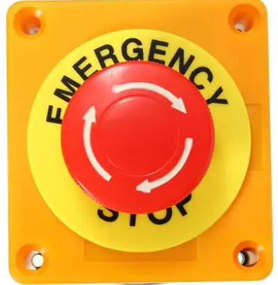
The EMERGENCY BUTTON (Manufacturer: SIFA LAB, Part ID: EMERGENCY) is a safety device designed to provide immediate response in critical situations. When pressed, it triggers an alert or action, such as stopping machinery, activating alarms, or signaling for help. This component is widely used in industrial, commercial, and residential environments where safety and quick response are paramount.
Explore Projects Built with EMERGENCY BUTTON
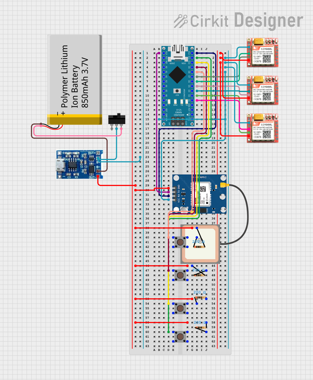

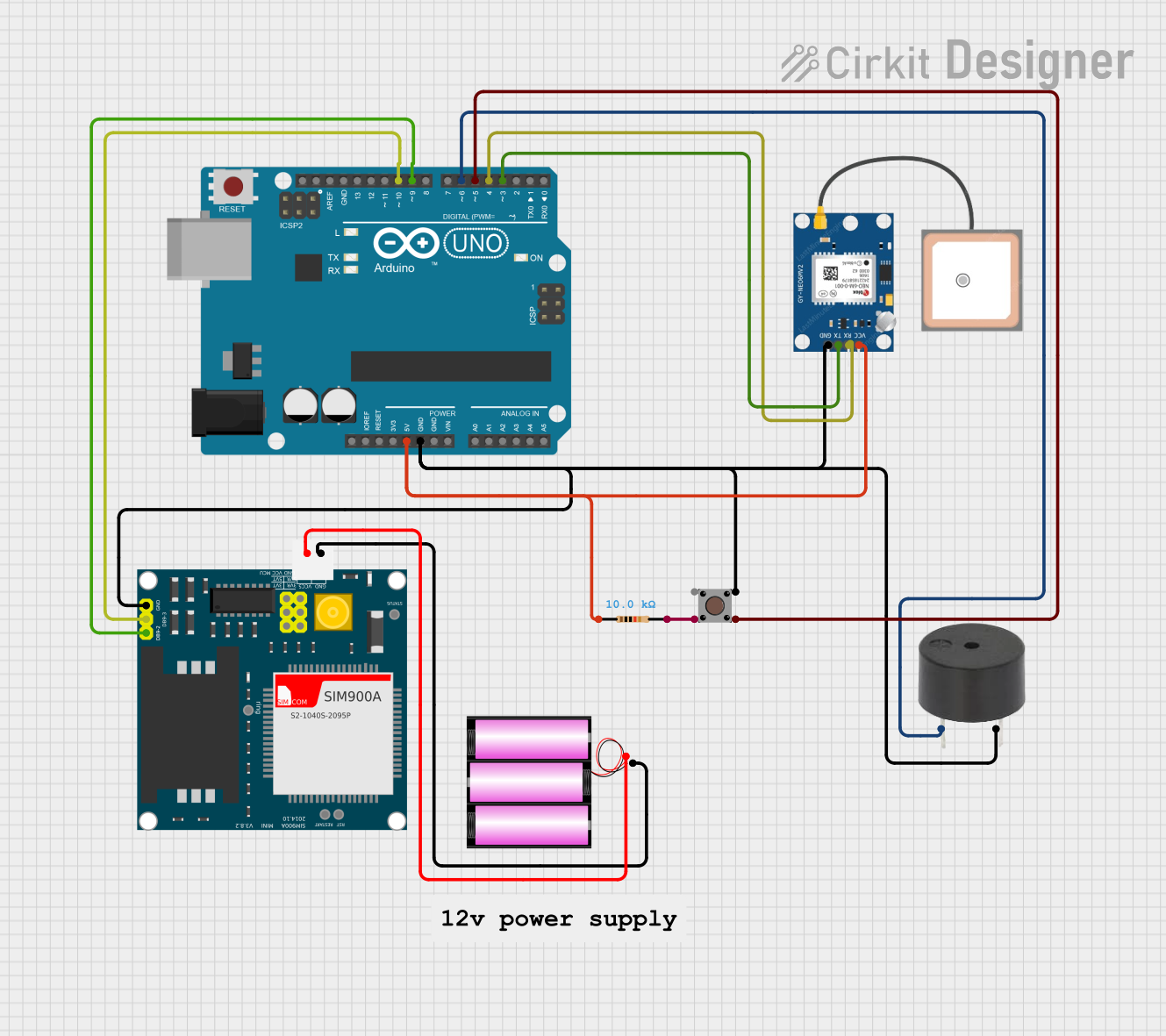
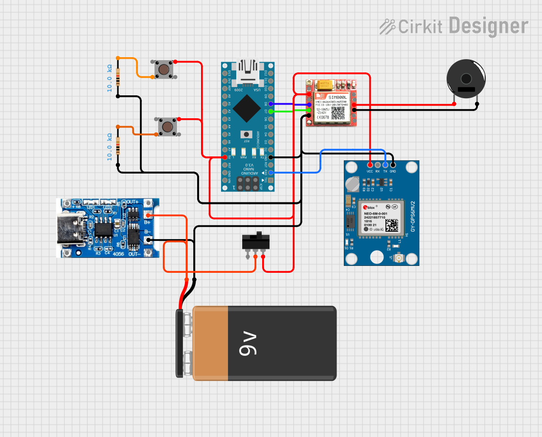
Explore Projects Built with EMERGENCY BUTTON
Common Applications and Use Cases
- Industrial machinery emergency stop systems
- Fire alarm and evacuation systems
- Medical alert systems
- Security systems for panic or distress signaling
- Public transportation emergency signaling
Technical Specifications
The following table outlines the key technical details of the EMERGENCY BUTTON:
| Parameter | Value |
|---|---|
| Manufacturer | SIFA LAB |
| Part ID | EMERGENCY |
| Operating Voltage | 12V DC |
| Maximum Current Rating | 3A |
| Contact Configuration | Normally Open (NO) or Normally Closed (NC) |
| Button Type | Latching (push to activate, twist to reset) |
| Operating Temperature | -20°C to 70°C |
| Mounting Type | Panel Mount |
| Dimensions | 40mm diameter, 50mm depth |
| Material | Polycarbonate (housing), metal contacts |
Pin Configuration and Descriptions
The EMERGENCY BUTTON has the following pin configuration:
| Pin | Label | Description |
|---|---|---|
| 1 | NO | Normally Open contact. Closes the circuit when pressed. |
| 2 | NC | Normally Closed contact. Opens the circuit when pressed. |
| 3 | COM | Common terminal. Connects to either NO or NC based on circuit design. |
Usage Instructions
How to Use the Component in a Circuit
- Determine the Contact Configuration: Decide whether to use the Normally Open (NO) or Normally Closed (NC) contact based on your application.
- Use NO for circuits that should activate only when the button is pressed.
- Use NC for circuits that should deactivate when the button is pressed.
- Connect the Terminals:
- Connect the COM terminal to the power source or signal input.
- Connect the NO or NC terminal to the load or control circuit.
- Mount the Button: Secure the button in a panel or enclosure using the provided mounting hardware.
- Test the Circuit: Verify that pressing the button triggers the desired action and that the button resets properly.
Important Considerations and Best Practices
- Voltage and Current Ratings: Ensure the connected circuit does not exceed the button's maximum ratings (12V DC, 3A).
- Debouncing: If the button is used in a digital circuit, implement debouncing to avoid false triggers.
- Reset Mechanism: The button requires a manual twist to reset after activation. Ensure this is suitable for your application.
- Safety Compliance: Follow local safety regulations when integrating the button into critical systems.
Example: Connecting to an Arduino UNO
The EMERGENCY BUTTON can be used with an Arduino UNO to trigger an alert. Below is an example circuit and code:
Circuit
- Connect the COM terminal to the Arduino's GND.
- Connect the NO terminal to digital pin 2 on the Arduino.
- Use a pull-up resistor (10kΩ) between digital pin 2 and 5V to ensure a stable signal.
Code
// Emergency Button Example with Arduino UNO
// This code monitors the button state and triggers an alert when pressed.

const int buttonPin = 2;  // Pin connected to the NO terminal of the button
const int ledPin = 13;    // Built-in LED for alert indication

void setup() {
  pinMode(buttonPin, INPUT_PULLUP); // Set button pin as input with pull-up resistor
  pinMode(ledPin, OUTPUT);         // Set LED pin as output
  digitalWrite(ledPin, LOW);       // Ensure LED is off initially
  Serial.begin(9600);             // Initialize serial communication
}

void loop() {
  int buttonState = digitalRead(buttonPin); // Read the button state

  if (buttonState == LOW) { // Button pressed (NO contact closed)
    digitalWrite(ledPin, HIGH); // Turn on the LED
    Serial.println("Emergency Button Pressed!"); // Log the event
  } else {
    digitalWrite(ledPin, LOW); // Turn off the LED
  }

  delay(50); // Small delay for debouncing
}
Troubleshooting and FAQs
Common Issues and Solutions
| Issue | Possible Cause | Solution |
|---|---|---|
| Button does not trigger the circuit | Incorrect wiring or loose connections | Verify wiring and ensure secure connections. |
| Button does not reset after pressing | Reset mechanism not twisted properly | Twist the button clockwise to reset. |
| Circuit behaves erratically | Signal bouncing or noise | Add a hardware or software debounce solution. |
| Button feels stuck or hard to press | Dirt or debris in the mechanism | Clean the button and ensure smooth operation. |
FAQs
Can the button be used with AC circuits?
- No, the EMERGENCY BUTTON is rated for DC circuits only. Using it with AC may damage the component or cause unsafe operation.
What happens if the button is pressed accidentally?
- The button will trigger the connected circuit. Ensure proper placement and use protective covers if accidental presses are a concern.
Can I use the button outdoors?
- The button is not waterproof. Use a weatherproof enclosure for outdoor applications.
How do I know if the button is compatible with my system?
- Check the voltage and current requirements of your system and ensure they match the button's ratings (12V DC, 3A max).
By following this documentation, you can effectively integrate the SIFA LAB EMERGENCY BUTTON into your projects and ensure reliable operation in critical situations.