How to Use DFR1015: Examples, Pinouts, and Specs
Introduction
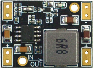
The DFR1015 is a compact and versatile DC motor driver module manufactured by DFRobot. It is designed to control the speed and direction of DC motors using an H-bridge configuration. This module supports bidirectional motor control and PWM (Pulse Width Modulation) for precise speed modulation, making it an excellent choice for robotics, automation, and other motor control applications.
Explore Projects Built with DFR1015
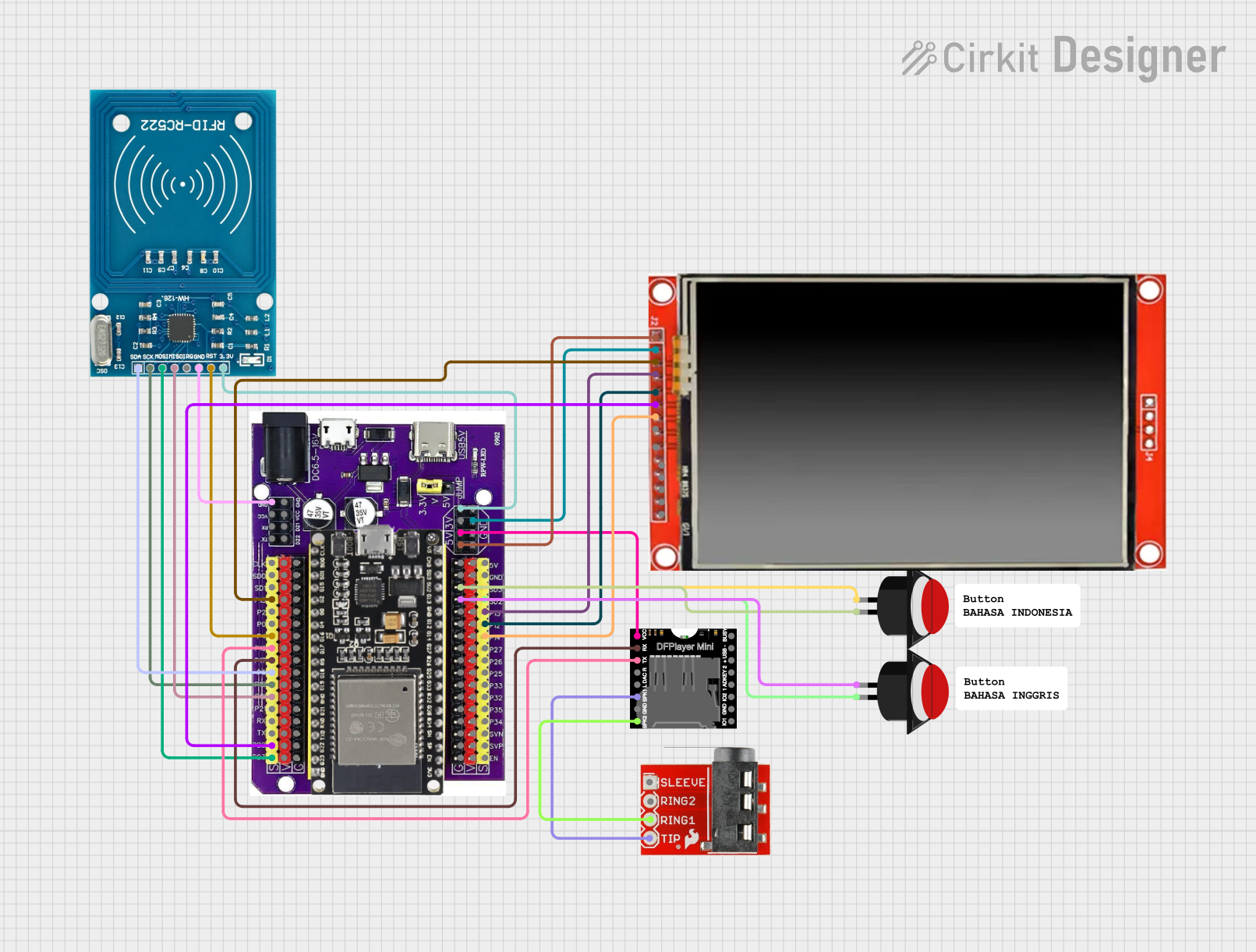

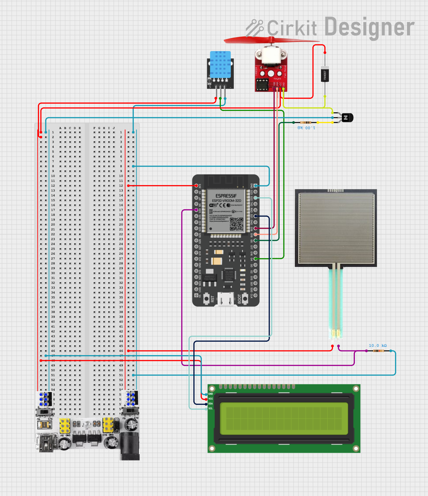

Explore Projects Built with DFR1015
Common Applications
- Robotics projects requiring motor control
- Automated conveyor systems
- Remote-controlled vehicles
- DIY motorized projects
- Educational and prototyping purposes
Technical Specifications
The DFR1015 is engineered to provide reliable and efficient motor control. Below are its key technical specifications:
| Parameter | Value |
|---|---|
| Manufacturer | DFRobot |
| Part Number | DFR1015 |
| Operating Voltage | 6V to 12V DC |
| Maximum Output Current | 1.5A per channel |
| Control Logic Voltage | 3.3V or 5V (logic level compatible) |
| Motor Channels | 1 (single motor control) |
| Control Interface | PWM and direction pins |
| Configuration | H-bridge |
| Dimensions | 30mm x 20mm x 10mm |
| Weight | 10g |
Pin Configuration and Descriptions
The DFR1015 module has a simple pinout for easy integration into your projects. Below is the pin configuration:
| Pin | Name | Description |
|---|---|---|
| 1 | VIN | Power input for the motor driver (6V to 12V DC). |
| 2 | GND | Ground connection. |
| 3 | PWM | PWM input for speed control (3.3V or 5V logic level). |
| 4 | DIR | Direction control input (HIGH for forward, LOW for reverse). |
| 5 | OUT1 | Motor output terminal 1. |
| 6 | OUT2 | Motor output terminal 2. |
Usage Instructions
The DFR1015 is straightforward to use in a circuit. Follow the steps below to integrate it into your project:
Connecting the DFR1015
- Power Supply: Connect the VIN pin to a DC power source (6V to 12V) and the GND pin to the ground of your circuit.
- Motor Connections: Connect the motor terminals to the OUT1 and OUT2 pins.
- Control Pins:
- Connect the PWM pin to a PWM-capable pin on your microcontroller (e.g., Arduino).
- Connect the DIR pin to a digital output pin on your microcontroller for direction control.
Example Circuit with Arduino UNO
Below is an example of how to connect the DFR1015 to an Arduino UNO:
- VIN: Connect to an external 12V power supply.
- GND: Connect to the Arduino GND.
- PWM: Connect to Arduino pin 9 (PWM-capable).
- DIR: Connect to Arduino pin 8.
- OUT1 and OUT2: Connect to the DC motor terminals.
Example Arduino Code
The following Arduino code demonstrates how to control the speed and direction of a DC motor using the DFR1015:
// Define pin connections
const int pwmPin = 9;  // PWM pin for speed control
const int dirPin = 8;  // Direction control pin

void setup() {
  // Set pin modes
  pinMode(pwmPin, OUTPUT);
  pinMode(dirPin, OUTPUT);
}

void loop() {
  // Set motor direction to forward
  digitalWrite(dirPin, HIGH);

  // Gradually increase motor speed
  for (int speed = 0; speed <= 255; speed += 5) {
    analogWrite(pwmPin, speed);  // Set PWM duty cycle
    delay(50);                   // Wait for 50ms
  }

  delay(1000);  // Run at full speed for 1 second

  // Set motor direction to reverse
  digitalWrite(dirPin, LOW);

  // Gradually decrease motor speed
  for (int speed = 255; speed >= 0; speed -= 5) {
    analogWrite(pwmPin, speed);  // Set PWM duty cycle
    delay(50);                   // Wait for 50ms
  }

  delay(1000);  // Pause before repeating
}
Important Considerations
- Ensure the motor's voltage and current ratings are within the DFR1015's specifications.
- Use a proper heat sink or cooling mechanism if the module operates near its maximum current rating for extended periods.
- Always connect the GND of the DFR1015 to the GND of your microcontroller to ensure proper operation.
Troubleshooting and FAQs
Common Issues and Solutions
Motor not spinning:
- Verify that the VIN pin is receiving the correct voltage (6V to 12V).
- Check the PWM and DIR pin connections to ensure they are properly connected to the microcontroller.
- Ensure the motor is functional and connected correctly to OUT1 and OUT2.
Motor spins in the wrong direction:
- Reverse the logic level on the DIR pin (HIGH for forward, LOW for reverse).
- Alternatively, swap the motor connections on OUT1 and OUT2.
Motor speed is inconsistent:
- Ensure the PWM signal is stable and within the correct frequency range.
- Check for loose connections or insufficient power supply.
Module overheating:
- Ensure the motor's current draw does not exceed 1.5A.
- Add a heat sink or improve ventilation around the module.
FAQs
Q1: Can I use the DFR1015 with a 3.3V microcontroller?
Yes, the DFR1015 is compatible with both 3.3V and 5V logic levels.
Q2: What type of motors can I control with the DFR1015?
The DFR1015 is designed for brushed DC motors with a voltage range of 6V to 12V.
Q3: Can I control two motors with this module?
No, the DFR1015 is a single-channel motor driver and can control only one motor.
Q4: What is the maximum PWM frequency supported?
The DFR1015 supports PWM frequencies up to 20kHz, which is suitable for most applications.
By following this documentation, you can effectively integrate the DFR1015 into your projects and achieve precise motor control.