How to Use ESP32: Examples, Pinouts, and Specs
Introduction
The ESP32 is a low-cost, low-power system on a chip (SoC) developed by Espressif Systems. It features integrated Wi-Fi and Bluetooth capabilities, making it an ideal choice for Internet of Things (IoT) applications, smart devices, and embedded systems. The ESP32 is highly versatile, offering dual-core processing, a wide range of GPIO pins, and support for various communication protocols.
Explore Projects Built with ESP32


Explore Projects Built with ESP32
Common Applications and Use Cases
- IoT devices (e.g., smart home systems, environmental monitoring)
- Wireless communication hubs
- Wearable devices
- Robotics and automation
- Data logging and remote sensing
- Prototyping and educational projects
Technical Specifications
Key Technical Details
| Feature | Specification |
|---|---|
| Processor | Dual-core Xtensa® 32-bit LX6 microprocessor |
| Clock Speed | Up to 240 MHz |
| Flash Memory | 4 MB (varies by module) |
| SRAM | 520 KB |
| Wi-Fi | 802.11 b/g/n (2.4 GHz) |
| Bluetooth | Bluetooth 4.2 and BLE |
| Operating Voltage | 3.0V - 3.6V |
| GPIO Pins | Up to 34 (multiplexed with other functions) |
| ADC Channels | 18 (12-bit resolution) |
| DAC Channels | 2 (8-bit resolution) |
| Communication Interfaces | UART, SPI, I2C, I2S, CAN, PWM |
| Power Consumption | Ultra-low power (varies by mode) |
| Operating Temperature | -40°C to 125°C |
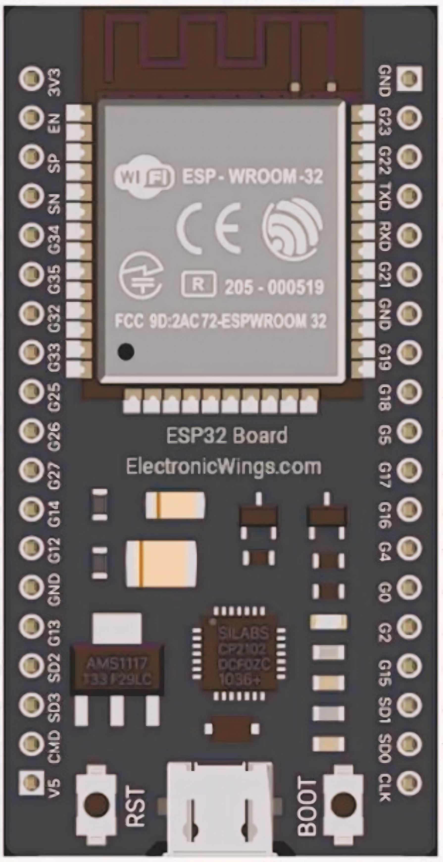
Pin Configuration and Descriptions
The ESP32 has multiple variants (e.g., ESP32-WROOM-32, ESP32-WROVER), but the pinout for the ESP32-WROOM-32 module is commonly used. Below is a summary of the key pins:
| Pin Name | Functionality | Description |
|---|---|---|
| GPIO0 | Input/Output, Boot Mode Selection | Used for boot mode selection during startup. |
| GPIO2 | Input/Output, ADC, PWM | General-purpose pin with ADC and PWM support. |
| GPIO4 | Input/Output, ADC, PWM | General-purpose pin with ADC and PWM support. |
| GPIO5 | Input/Output, ADC, PWM, SPI | General-purpose pin with SPI support. |
| GPIO12 | Input/Output, ADC, PWM, Touch Sensor | Supports touch sensing and ADC functionality. |
| GPIO13 | Input/Output, ADC, PWM, Touch Sensor | Supports touch sensing and ADC functionality. |
| GPIO14 | Input/Output, ADC, PWM, SPI | General-purpose pin with SPI support. |
| GPIO15 | Input/Output, ADC, PWM, Touch Sensor | Supports touch sensing and ADC functionality. |
| GPIO16 | Input/Output | General-purpose pin. |
| GPIO17 | Input/Output | General-purpose pin. |
| EN | Enable | Resets the chip when pulled low. |
| 3V3 | Power Supply | Provides 3.3V power to the module. |
| GND | Ground | Ground connection. |
Note: Some GPIO pins have specific restrictions or are used during boot. Refer to the ESP32 datasheet for detailed pin behavior.
Usage Instructions
How to Use the ESP32 in a Circuit
- Power Supply: Provide a stable 3.3V power supply to the
3V3pin. Avoid exceeding 3.6V to prevent damage. - Boot Mode: Connect GPIO0 to GND during startup to enter bootloader mode for programming.
- Programming: Use a USB-to-serial adapter or development board (e.g., ESP32 DevKit) to upload code via the UART interface.
- GPIO Usage: Configure GPIO pins as input or output in your code. Be mindful of pins with special functions (e.g., ADC, PWM).
- Wi-Fi and Bluetooth: Use the ESP-IDF or Arduino IDE libraries to configure and manage wireless communication.
Important Considerations and Best Practices
- Voltage Levels: Ensure all connected peripherals operate at 3.3V logic levels. Use level shifters if interfacing with 5V devices.
- Power Consumption: Use deep sleep mode to minimize power usage in battery-powered applications.
- Antenna Placement: Avoid placing metal objects near the onboard antenna to ensure optimal wireless performance.
- Heat Management: The ESP32 can get warm during operation. Ensure proper ventilation in enclosed designs.
Example Code for Arduino IDE
Below is an example of how to connect the ESP32 to a Wi-Fi network and blink an LED:
#include <WiFi.h> // Include the Wi-Fi library

const char* ssid = "Your_SSID";       // Replace with your Wi-Fi SSID
const char* password = "Your_PASSWORD"; // Replace with your Wi-Fi password
const int ledPin = 2;                 // GPIO2 is often used for onboard LEDs

void setup() {
  pinMode(ledPin, OUTPUT);            // Set GPIO2 as an output
  Serial.begin(115200);               // Initialize serial communication
  Serial.println("Connecting to Wi-Fi...");

  WiFi.begin(ssid, password);         // Start Wi-Fi connection
  while (WiFi.status() != WL_CONNECTED) {
    delay(500);                       // Wait for connection
    Serial.print(".");
  }
  Serial.println("\nWi-Fi connected!");
  Serial.print("IP Address: ");
  Serial.println(WiFi.localIP());     // Print the device's IP address
}

void loop() {
  digitalWrite(ledPin, HIGH);         // Turn the LED on
  delay(1000);                        // Wait for 1 second
  digitalWrite(ledPin, LOW);          // Turn the LED off
  delay(1000);                        // Wait for 1 second
}
Note: Replace
Your_SSIDandYour_PASSWORDwith your Wi-Fi credentials.
Troubleshooting and FAQs
Common Issues and Solutions
ESP32 Not Connecting to Wi-Fi
- Solution: Double-check the SSID and password. Ensure the Wi-Fi network is 2.4 GHz, as the ESP32 does not support 5 GHz networks.
GPIO Pins Not Working as Expected
- Solution: Verify that the pin is not being used for another function (e.g., boot mode). Consult the ESP32 datasheet for pin-specific details.
Device Not Detected by Computer
- Solution: Ensure the correct USB driver is installed for your USB-to-serial adapter. Use a known-good USB cable.
Frequent Resets or Instability
- Solution: Check the power supply. The ESP32 requires a stable 3.3V source with sufficient current (at least 500 mA).
FAQs
Q: Can the ESP32 operate on battery power?
- A: Yes, the ESP32 can operate on battery power. Use a 3.7V LiPo battery with a voltage regulator to provide 3.3V.
Q: How do I update the ESP32 firmware?
- A: Use the Espressif Flash Download Tool or the Arduino IDE to upload new firmware via the UART interface.
Q: Can I use the ESP32 with 5V logic devices?
- A: No, the ESP32 operates at 3.3V logic levels. Use level shifters to interface with 5V devices.