How to Use Adafruit PowerBoost 1000C: Examples, Pinouts, and Specs
Introduction
The Adafruit PowerBoost 1000C is a compact and versatile power management module designed to boost a 3.7V lithium polymer (LiPo) or lithium-ion battery to a stable 5V output. It is capable of delivering up to 1A of current, making it ideal for powering microcontrollers, single-board computers, and other 5V devices. Additionally, the module features an integrated battery charger, allowing you to charge the connected battery via a micro-USB port while simultaneously powering your device.
Explore Projects Built with Adafruit PowerBoost 1000C
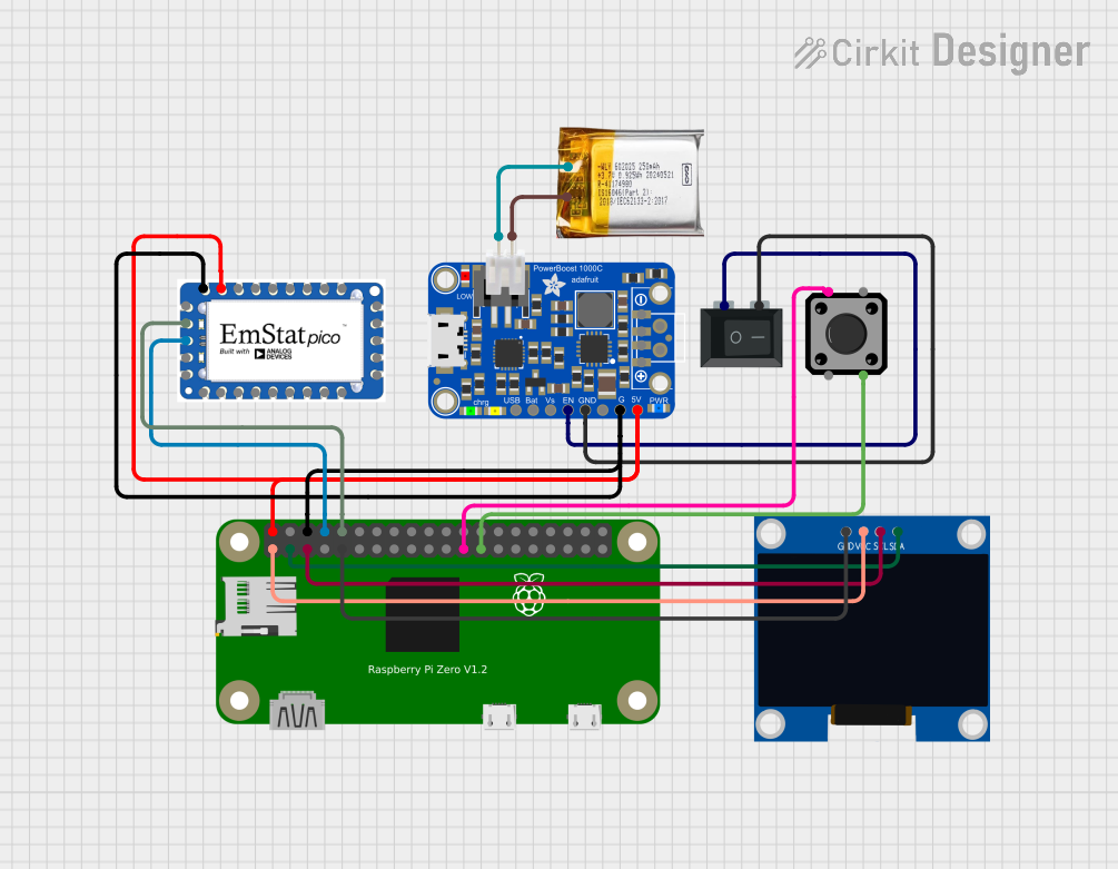


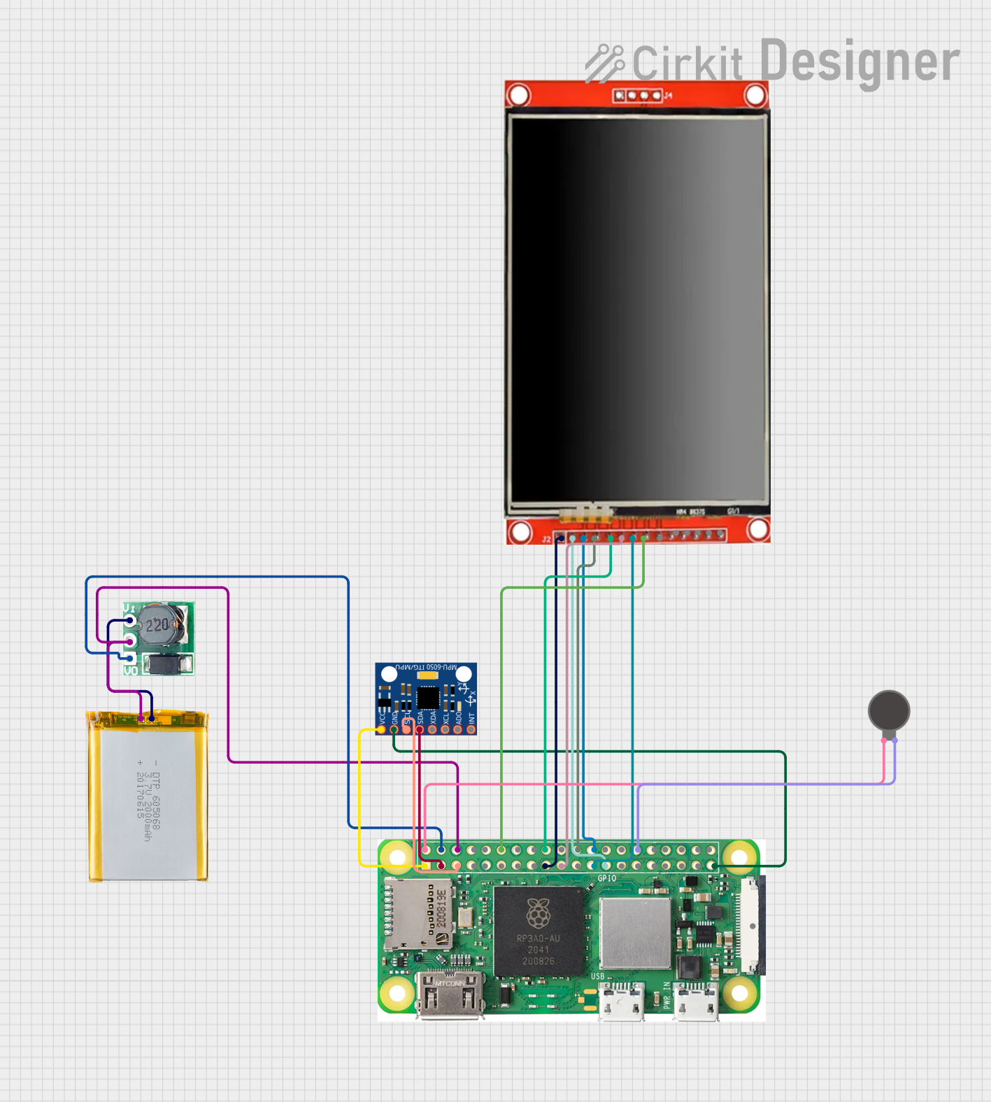
Explore Projects Built with Adafruit PowerBoost 1000C
Common Applications and Use Cases
- Portable electronics and battery-powered projects
- Powering microcontrollers like Arduino, Raspberry Pi, or ESP32
- Emergency power supplies for small devices
- Wearable technology
- Robotics and IoT devices
Technical Specifications
Key Technical Details
- Input Voltage (Battery): 3.7V nominal (LiPo/Li-ion battery)
- Input Voltage (USB): 5V via micro-USB
- Output Voltage: 5V DC
- Output Current: Up to 1A continuous
- Charging Current: 1A (maximum)
- Efficiency: Up to 90% (depending on load)
- Low-Battery Indicator: 3.2V threshold
- Dimensions: 22mm x 50mm x 5mm
- Weight: 5.7g
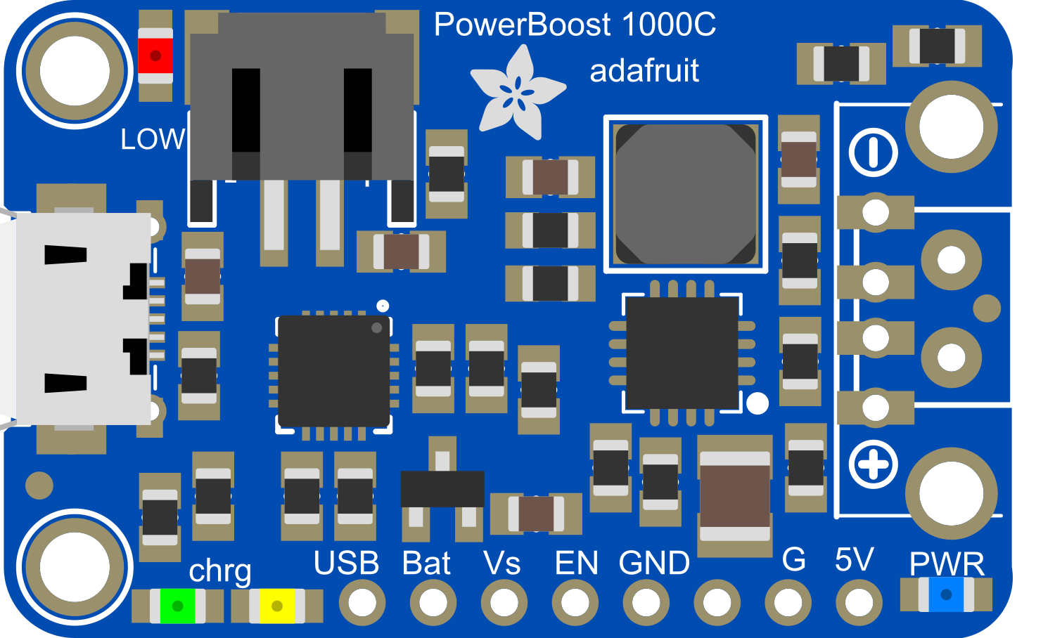
Pin Configuration and Descriptions
The Adafruit PowerBoost 1000C has several pins and connectors for input, output, and control. Below is a detailed description:
| Pin/Connector | Description |
|---|---|
| BAT | Battery input pin for connecting a 3.7V LiPo/Li-ion battery. |
| GND | Ground connection. |
| 5V | 5V output pin for powering external devices. |
| EN | Enable pin. Pull low to disable the 5V output. |
| LBO | Low-battery output indicator. Goes low when the battery voltage is below 3.2V. |
| USB | Micro-USB connector for charging the battery and powering the module. |
Usage Instructions
How to Use the Component in a Circuit
- Connect the Battery:
- Attach a 3.7V LiPo or Li-ion battery to the BAT and GND pins. Ensure correct polarity to avoid damage.
- Power the Module:
- Optionally, connect a 5V micro-USB cable to the USB port to charge the battery and power the module simultaneously.
- Connect the Load:
- Use the 5V and GND pins to power your external device. Ensure the load does not exceed 1A.
- Enable/Disable Output:
- Use the EN pin to control the 5V output. Pull the pin low to disable the output, or leave it floating for normal operation.
Important Considerations and Best Practices
- Battery Selection: Use only 3.7V LiPo or Li-ion batteries with a JST connector for safe operation.
- Heat Management: The module may heat up under high loads. Ensure proper ventilation or heat dissipation.
- Low-Battery Protection: Monitor the LBO pin to detect low battery conditions and prevent over-discharge.
- Charging Safety: Do not exceed the 1A charging current limit. Use a USB power source capable of supplying at least 1.5A for optimal performance.
Example: Using with Arduino UNO
The PowerBoost 1000C can be used to power an Arduino UNO. Below is an example setup:
- Connect the 5V pin of the PowerBoost to the 5V pin of the Arduino UNO.
- Connect the GND pin of the PowerBoost to the GND pin of the Arduino UNO.
- Optionally, monitor the LBO pin to detect low battery conditions.
Here is a simple Arduino sketch to monitor the LBO pin:
// Define the pin connected to the LBO (Low-Battery Output) signal
const int lboPin = 2;

void setup() {
  pinMode(lboPin, INPUT); // Set LBO pin as input
  Serial.begin(9600);     // Initialize serial communication
}

void loop() {
  int lboState = digitalRead(lboPin); // Read the LBO pin state

  if (lboState == LOW) {
    // If LBO is LOW, the battery voltage is below 3.2V
    Serial.println("Warning: Low battery detected!");
  } else {
    // If LBO is HIGH, the battery voltage is sufficient
    Serial.println("Battery voltage is sufficient.");
  }

  delay(1000); // Wait for 1 second before checking again
}
Troubleshooting and FAQs
Common Issues and Solutions
Module Overheating:
- Cause: High current draw or insufficient ventilation.
- Solution: Reduce the load or ensure proper airflow around the module.
No Output Voltage:
- Cause: Battery not connected, or the EN pin is pulled low.
- Solution: Check the battery connection and ensure the EN pin is not grounded.
Battery Not Charging:
- Cause: Insufficient USB power supply or damaged battery.
- Solution: Use a USB power source capable of supplying at least 1.5A and verify the battery's condition.
Low-Battery Indicator Always On:
- Cause: Battery voltage is consistently below 3.2V.
- Solution: Recharge the battery or replace it if it is damaged.
FAQs
Q1: Can I use the PowerBoost 1000C without a battery?
A1: Yes, you can power the module directly via the micro-USB port, but the low-battery indicator will not function.
Q2: What happens if the load exceeds 1A?
A2: The module may overheat, and the output voltage may drop. Prolonged overloading can damage the module.
Q3: Can I use this module to charge other types of batteries?
A3: No, the PowerBoost 1000C is specifically designed for 3.7V LiPo or Li-ion batteries. Using other types of batteries may result in damage or unsafe operation.
Q4: Is the module safe for continuous operation?
A4: Yes, as long as the load does not exceed 1A and proper heat dissipation is ensured, the module can operate continuously.