How to Use ESP32 WROOM-32U: Examples, Pinouts, and Specs
Introduction
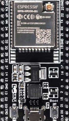
The ESP32 WROOM-32U, manufactured by Espressif, is a powerful and versatile microcontroller module designed for Internet of Things (IoT) applications. It features integrated Wi-Fi and Bluetooth capabilities, making it ideal for wireless communication in smart devices. With its dual-core processing, ample GPIO pins, and support for a wide range of peripherals, the ESP32 WROOM-32U is a popular choice for developers building connected devices.
Explore Projects Built with ESP32 WROOM-32U


Explore Projects Built with ESP32 WROOM-32U
Common Applications and Use Cases
- Smart home devices (e.g., smart lights, thermostats, and security systems)
- Industrial IoT (IIoT) applications
- Wearable devices
- Wireless sensor networks
- Robotics and automation
- Prototyping and development of connected systems
Technical Specifications
The ESP32 WROOM-32U is packed with features that make it suitable for a variety of applications. Below are its key technical specifications:
| Parameter | Value |
|---|---|
| Manufacturer | Espressif |
| Part ID | WROOM-32U |
| Microcontroller | ESP32-D0WD |
| Wireless Connectivity | Wi-Fi 802.11 b/g/n, Bluetooth v4.2 BR/EDR and BLE |
| CPU | Dual-core Xtensa® 32-bit LX6 processor, up to 240 MHz |
| Flash Memory | 4 MB (external SPI flash) |
| SRAM | 520 KB |
| GPIO Pins | 36 (multiplexed for various functions) |
| Operating Voltage | 3.0V to 3.6V |
| Power Consumption | 5 µA in deep sleep, ~240 mA during active Wi-Fi transmission |
| Operating Temperature | -40°C to +85°C |
| Dimensions | 18 mm x 25.5 mm |
| Antenna | External antenna (U.FL connector) |
Pin Configuration and Descriptions
The ESP32 WROOM-32U has 38 pins, with multiple functions multiplexed on each pin. Below is a table summarizing the key pin functions:
| Pin Number | Pin Name | Function |
|---|---|---|
| 1 | EN | Enable pin (active high, used to reset the module) |
| 2 | IO0 | GPIO0, used for boot mode selection (must be LOW during flashing) |
| 3 | IO2 | GPIO2, general-purpose I/O |
| 4 | IO4 | GPIO4, general-purpose I/O |
| 5 | IO5 | GPIO5, general-purpose I/O |
| 6 | IO12 | GPIO12, general-purpose I/O, also used for bootstrapping |
| 7 | IO13 | GPIO13, general-purpose I/O, supports PWM and ADC |
| 8 | IO14 | GPIO14, general-purpose I/O, supports PWM and ADC |
| 9 | IO15 | GPIO15, general-purpose I/O, supports PWM and ADC |
| 10 | IO16 | GPIO16, general-purpose I/O, supports UART RX |
| 11 | IO17 | GPIO17, general-purpose I/O, supports UART TX |
| 12 | GND | Ground |
| 13 | 3V3 | 3.3V power supply |
| 14 | TXD0 | UART0 Transmit |
| 15 | RXD0 | UART0 Receive |
| 16 | IO18 | GPIO18, general-purpose I/O, supports SPI CLK |
| 17 | IO19 | GPIO19, general-purpose I/O, supports SPI MISO |
| 18 | IO21 | GPIO21, general-purpose I/O, supports I2C SDA |
| 19 | IO22 | GPIO22, general-purpose I/O, supports I2C SCL |
| 20 | IO23 | GPIO23, general-purpose I/O, supports SPI MOSI |
Note: Not all pins are available for general-purpose use, as some are reserved for internal functions. Refer to the official datasheet for detailed pin multiplexing information.
Usage Instructions
How to Use the ESP32 WROOM-32U in a Circuit
- Power Supply: Provide a stable 3.3V power supply to the module. Avoid exceeding 3.6V to prevent damage.
- Boot Mode for Flashing: To flash firmware, connect GPIO0 to GND and reset the module. After flashing, disconnect GPIO0 from GND.
- External Antenna: Connect an external antenna to the U.FL connector for optimal wireless performance.
- GPIO Usage: Configure GPIO pins as input, output, or for specific peripherals (e.g., UART, SPI, I2C) in your firmware.
- Programming: Use the Arduino IDE, Espressif's ESP-IDF, or other compatible development environments to program the module.
Important Considerations and Best Practices
- Decoupling Capacitors: Place decoupling capacitors (e.g., 0.1 µF) near the power pins to reduce noise.
- Antenna Placement: Ensure the external antenna is placed away from metal objects to avoid signal interference.
- Deep Sleep Mode: Use deep sleep mode to minimize power consumption in battery-powered applications.
- Voltage Levels: Ensure all GPIO inputs are within the 0V to 3.3V range to avoid damage.
Example Code for Arduino UNO
Below is an example of how to use the ESP32 WROOM-32U with the Arduino IDE to blink an LED connected to GPIO2:
// Example: Blink an LED connected to GPIO2 on the ESP32 WROOM-32U

// Define the GPIO pin for the LED
#define LED_PIN 2

void setup() {
  // Initialize the LED pin as an output
  pinMode(LED_PIN, OUTPUT);
}

void loop() {
  // Turn the LED on
  digitalWrite(LED_PIN, HIGH);
  delay(1000); // Wait for 1 second

  // Turn the LED off
  digitalWrite(LED_PIN, LOW);
  delay(1000); // Wait for 1 second
}
Note: Ensure the ESP32 WROOM-32U is properly connected to your computer via a USB-to-serial adapter for programming.
Troubleshooting and FAQs
Common Issues and Solutions
Module Not Responding
- Cause: Incorrect power supply or wiring.
- Solution: Verify the power supply is 3.3V and check all connections.
Cannot Flash Firmware
- Cause: GPIO0 is not pulled LOW during flashing.
- Solution: Ensure GPIO0 is connected to GND and reset the module before flashing.
Wi-Fi Connection Fails
- Cause: Incorrect SSID or password.
- Solution: Double-check the Wi-Fi credentials in your code.
Bluetooth Not Discoverable
- Cause: Bluetooth not initialized in firmware.
- Solution: Ensure the Bluetooth stack is properly configured in your code.
FAQs
Q: Can the ESP32 WROOM-32U operate on 5V?
A: No, the module operates on 3.3V. Use a voltage regulator if your power source is 5V.Q: How do I reset the module?
A: Pull the EN pin LOW momentarily to reset the module.Q: Can I use the ESP32 WROOM-32U with the Arduino IDE?
A: Yes, the module is fully compatible with the Arduino IDE. Install the ESP32 board package to get started.Q: What is the maximum range of the Wi-Fi?
A: The range depends on the environment but typically reaches up to 100 meters in open space.
By following this documentation, you can effectively integrate the ESP32 WROOM-32U into your projects and troubleshoot common issues.