Cirkit Designer Logo
Cirkit Designer
Your all-in-one circuit design IDE
Home / 
Component Documentation

How to Use Adafruit MatrixPortal M4: Examples, Pinouts, and Specs

Image of Adafruit MatrixPortal M4
Cirkit Designer LogoDesign with Adafruit MatrixPortal M4 in Cirkit Designer

Introduction

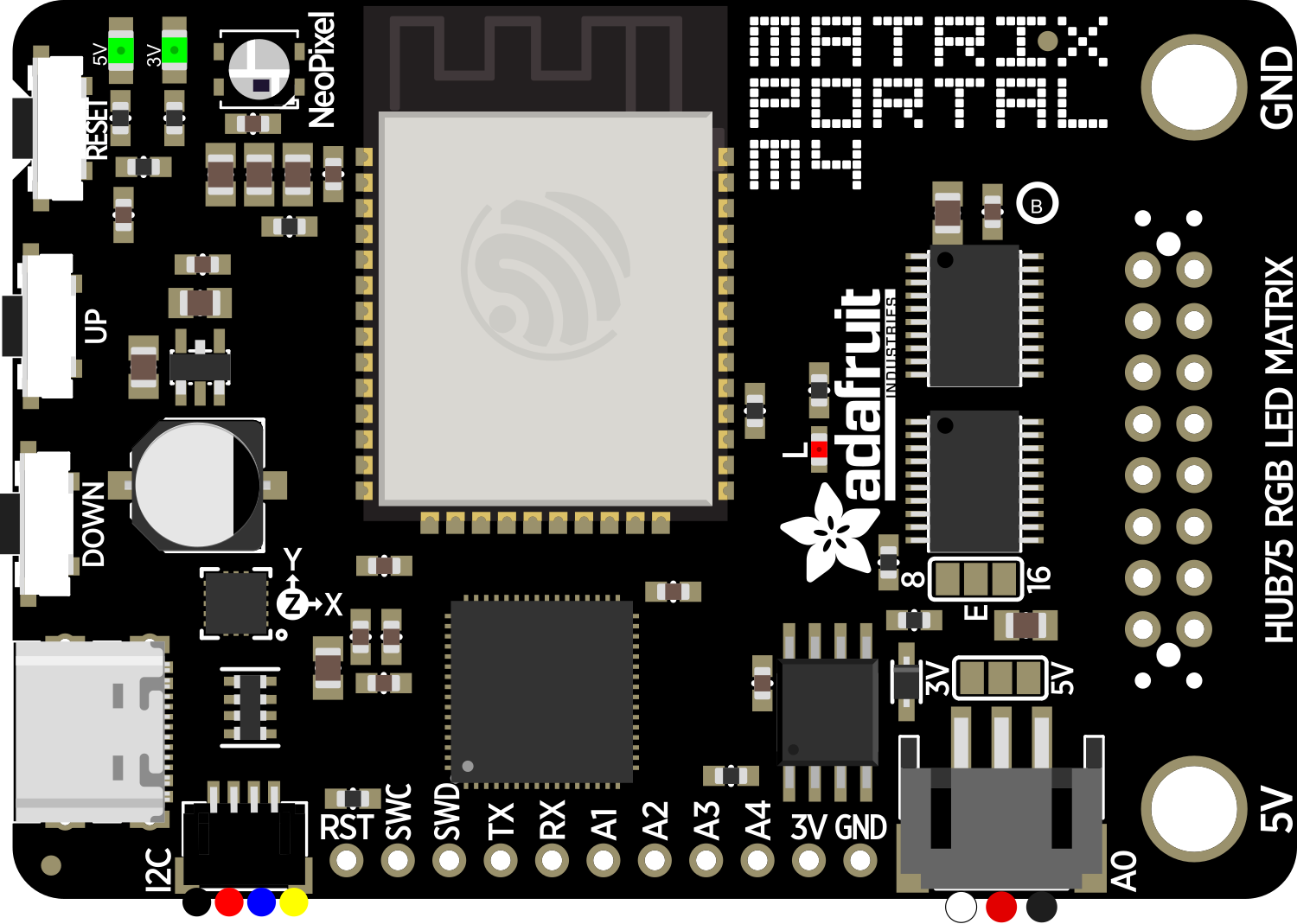
The Adafruit MatrixPortal M4 is a versatile and powerful development board designed for driving RGB LED matrices. It is built around the high-performance SAMD51 microcontroller and is perfect for creating eye-catching displays, interactive art installations, and advanced Internet of Things (IoT) projects. With its onboard connectivity and ease of use, the MatrixPortal M4 is an ideal choice for hobbyists, educators, and professionals looking to bring their LED matrix projects to life.

Explore Projects Built with Adafruit MatrixPortal M4

Use Cirkit Designer to design, explore, and prototype these projects online. Some projects support real-time simulation. Click "Open Project" to start designing instantly!
Arduino UNO-Based Interactive LED Game with 8x8 Matrix and TM1637 Display
Image of Gra_na_refleks: A project utilizing Adafruit MatrixPortal M4 in a practical application
This circuit is a game system controlled by an Arduino UNO, featuring an 8x8 LED matrix, a 4x4 keypad, and a TM1637 4-digit display. The user interacts with the game via the keypad, and the game state is displayed on the LED matrix and the TM1637 display, with power supplied by a 9V battery.
Cirkit Designer LogoOpen Project in Cirkit Designer
Arduino Mega 2560-Based Smart Home Control System with LCD Display and Flame Sensor
Image of Copy of schoolproject (1): A project utilizing Adafruit MatrixPortal M4 in a practical application
This circuit is a multi-functional embedded system featuring an Arduino Mega 2560 microcontroller that interfaces with a 4x4 membrane keypad, a 20x4 I2C LCD, an 8x8 LED matrix, a DS3231 RTC module, a passive buzzer, and a KY-026 flame sensor. The system is powered by a 5V PSU and is designed to provide real-time clock functionality, user input via the keypad, visual output on the LCD and LED matrix, and flame detection with an audible alert.
Cirkit Designer LogoOpen Project in Cirkit Designer
Arduino Mega 2560 Controlled Interactive Display with RTC, Keypad, and Flame Sensor
Image of schoolproject: A project utilizing Adafruit MatrixPortal M4 in a practical application
This circuit features an Arduino Mega 2560 microcontroller interfaced with a variety of components for input and output. It includes a 4x4 membrane matrix keypad for user input, a 20x4 LCD with I2C interface for display, a DS3231 RTC for real-time clock functionality, a passive buzzer for audio feedback, an 8x8 LED matrix for visual output, and a KY-026 flame sensor for detecting fire or flame presence. The circuit is powered by a 5V power supply unit, and the Arduino Mega coordinates the interaction between these components, although the provided code is a template without specific functionality.
Cirkit Designer LogoOpen Project in Cirkit Designer
Arduino 101 Based Touch-Controlled LED Matrix with DHT22 Sensor Integration
Image of PROJECT TOUCH SENSOR: A project utilizing Adafruit MatrixPortal M4 in a practical application
This circuit features an Arduino 101 microcontroller connected to a touch sensor, an 8x8 LED matrix, and a DHT22 temperature and humidity sensor. The Arduino provides power to all components and interfaces with the touch sensor via a digital I/O pin and the DHT22 sensor via another digital I/O pin. It controls the 8x8 LED matrix using SPI communication, with dedicated pins for data, clock, and chip select.
Cirkit Designer LogoOpen Project in Cirkit Designer

Explore Projects Built with Adafruit MatrixPortal M4

Use Cirkit Designer to design, explore, and prototype these projects online. Some projects support real-time simulation. Click "Open Project" to start designing instantly!
Image of Gra_na_refleks: A project utilizing Adafruit MatrixPortal M4 in a practical application
Arduino UNO-Based Interactive LED Game with 8x8 Matrix and TM1637 Display
This circuit is a game system controlled by an Arduino UNO, featuring an 8x8 LED matrix, a 4x4 keypad, and a TM1637 4-digit display. The user interacts with the game via the keypad, and the game state is displayed on the LED matrix and the TM1637 display, with power supplied by a 9V battery.
Cirkit Designer LogoOpen Project in Cirkit Designer
Image of Copy of schoolproject (1): A project utilizing Adafruit MatrixPortal M4 in a practical application
Arduino Mega 2560-Based Smart Home Control System with LCD Display and Flame Sensor
This circuit is a multi-functional embedded system featuring an Arduino Mega 2560 microcontroller that interfaces with a 4x4 membrane keypad, a 20x4 I2C LCD, an 8x8 LED matrix, a DS3231 RTC module, a passive buzzer, and a KY-026 flame sensor. The system is powered by a 5V PSU and is designed to provide real-time clock functionality, user input via the keypad, visual output on the LCD and LED matrix, and flame detection with an audible alert.
Cirkit Designer LogoOpen Project in Cirkit Designer
Image of schoolproject: A project utilizing Adafruit MatrixPortal M4 in a practical application
Arduino Mega 2560 Controlled Interactive Display with RTC, Keypad, and Flame Sensor
This circuit features an Arduino Mega 2560 microcontroller interfaced with a variety of components for input and output. It includes a 4x4 membrane matrix keypad for user input, a 20x4 LCD with I2C interface for display, a DS3231 RTC for real-time clock functionality, a passive buzzer for audio feedback, an 8x8 LED matrix for visual output, and a KY-026 flame sensor for detecting fire or flame presence. The circuit is powered by a 5V power supply unit, and the Arduino Mega coordinates the interaction between these components, although the provided code is a template without specific functionality.
Cirkit Designer LogoOpen Project in Cirkit Designer
Image of PROJECT TOUCH SENSOR: A project utilizing Adafruit MatrixPortal M4 in a practical application
Arduino 101 Based Touch-Controlled LED Matrix with DHT22 Sensor Integration
This circuit features an Arduino 101 microcontroller connected to a touch sensor, an 8x8 LED matrix, and a DHT22 temperature and humidity sensor. The Arduino provides power to all components and interfaces with the touch sensor via a digital I/O pin and the DHT22 sensor via another digital I/O pin. It controls the 8x8 LED matrix using SPI communication, with dedicated pins for data, clock, and chip select.
Cirkit Designer LogoOpen Project in Cirkit Designer

Common Applications and Use Cases

  • Digital signage and message boards
  • Interactive art installations
  • Data visualization displays
  • Gaming and entertainment systems
  • Educational tools for teaching programming and electronics
  • Custom clocks and timers
  • IoT devices with visual feedback

Technical Specifications

Key Technical Details

  • Microcontroller: ATSAMD51J19
  • Clock Speed: 120 MHz
  • Flash Memory: 512 KB
  • RAM: 192 KB
  • Input Voltage (VIN): 4.5V to 6.0V
  • Logic Level: 3.3V
  • Connectivity: Wi-Fi (ESP32-S0WD), USB-C

Pin Configuration and Descriptions

Pin Number Name Description
1 GND Ground
2 VBUS USB input voltage (5V)
3 EN Enable; can be cut to disable auto-reset
... ... ...
n IO36 General purpose I/O pin

Note: This is a partial list. Refer to the official datasheet for the full pinout.

Usage Instructions

How to Use the Component in a Circuit

  1. Powering the MatrixPortal M4: Connect a 5V power supply to the VIN and GND pins, or power the board via the USB-C port.
  2. Connecting to an LED Matrix: Use the onboard connectors to attach a compatible RGB LED matrix. Ensure the matrix's voltage and current requirements are compatible with the MatrixPortal M4.
  3. Programming the Board: The MatrixPortal M4 can be programmed using the Arduino IDE or CircuitPython. Select the appropriate board and port before uploading your code.

Important Considerations and Best Practices

  • Always disconnect the power source before making or altering connections.
  • Verify the orientation of the LED matrix connector before attaching it to the board.
  • Use a sufficient power supply to handle the current draw of the LED matrix, especially for larger displays.
  • Consider using a level shifter if you need to interface with other components that operate at different logic levels.

Troubleshooting and FAQs

Common Issues Users Might Face

  • LED Matrix Not Lighting Up: Check the power supply and connections. Ensure the code is correctly uploaded and running.
  • Flickering or Incorrect Colors: This may indicate a timing issue or insufficient power. Verify the power supply and refresh rate settings in your code.
  • Board Not Recognized by Computer: Ensure the USB cable is fully inserted and functional. Try a different USB port or cable if necessary.

Solutions and Tips for Troubleshooting

  • Double-check all connections for solid contact and correct orientation.
  • Use the serial monitor to debug and check for error messages or output.
  • Update to the latest firmware and libraries to ensure compatibility and fix known issues.

FAQs

Q: Can I chain multiple LED matrices together? A: Yes, the MatrixPortal M4 supports chaining of compatible LED matrices. Ensure your power supply can handle the increased current draw.

Q: What programming languages can I use with the MatrixPortal M4? A: The board supports programming with Arduino (C/C++) and CircuitPython.

Q: How do I update the firmware on the ESP32 module? A: Follow the instructions provided by Adafruit for updating the ESP32 firmware using the provided utility.

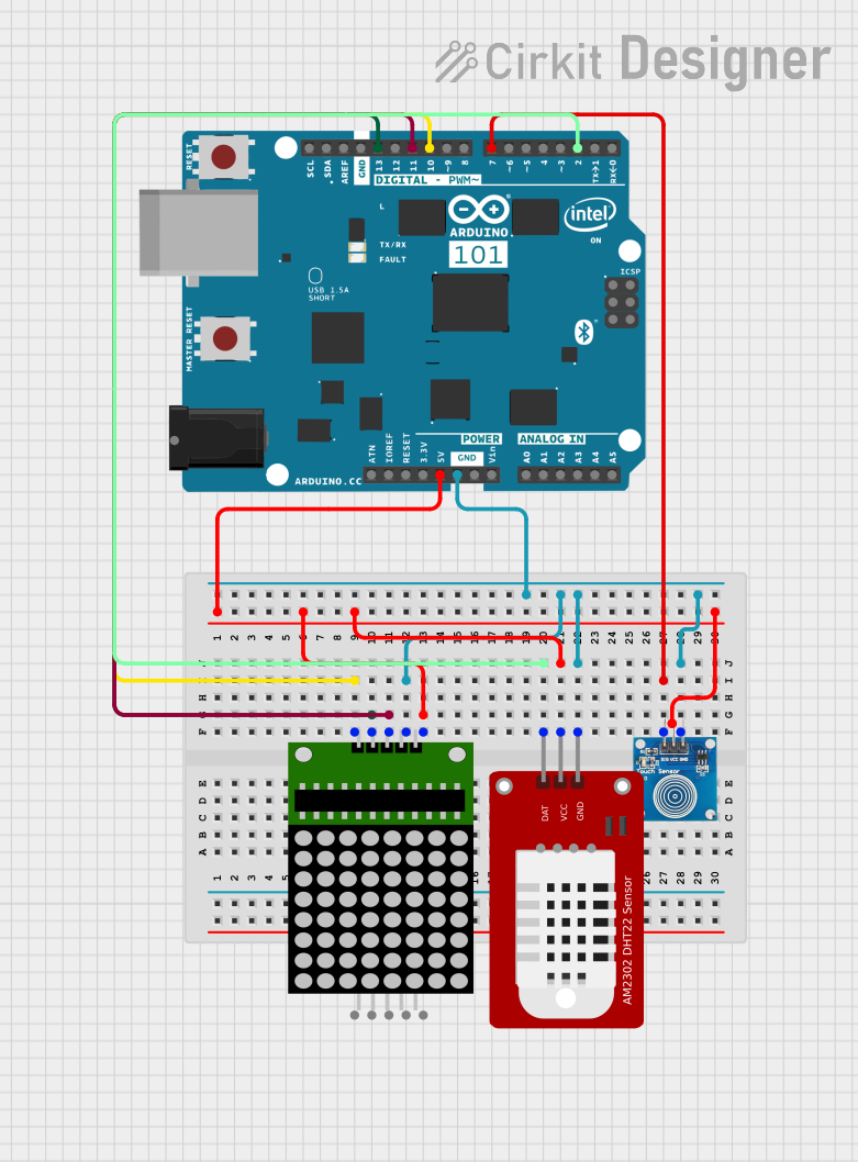
Example Code for Arduino UNO

Below is a simple example code snippet that demonstrates how to light up an LED on the matrix. This code is for illustrative purposes and assumes you have the necessary libraries installed.

#include <Adafruit_GFX.h>   // Core graphics library
#include <Adafruit_LEDBackpack.h>

Adafruit_BicolorMatrix matrix = Adafruit_BicolorMatrix();

void setup() {
  matrix.begin(0x70);  // Start the LED matrix using the I2C address
}

void loop() {
  matrix.clear();      // Clear the matrix display
  matrix.drawPixel(0, 0, LED_GREEN);  // Light up one LED in the top-left corner
  matrix.writeDisplay();  // Update the display with the new LED state
  delay(500);
  matrix.clear();      // Clear the display again
  matrix.writeDisplay();  // Update to show the cleared state
  delay(500);
}

Note: This code is for demonstration purposes and may require modifications to work with your specific hardware setup. Always refer to the official Adafruit libraries and documentation for the MatrixPortal M4 for the most accurate and up-to-date information.