
How to Use SWITCH-MOMENTARY-2: Examples, Pinouts, and Specs
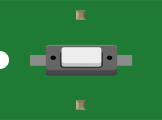
 Design with SWITCH-MOMENTARY-2 in Cirkit Designer
Introduction
The SWITCH-MOMENTARY-2 is a simple yet versatile electronic component designed to close a circuit only while it is being pressed. This momentary switch is commonly used for temporary actions, such as triggering a function, activating a device, or sending a signal in a circuit. Its compact design and ease of use make it a popular choice in a wide range of applications, including consumer electronics, prototyping, and industrial control systems.
Explore Projects Built with SWITCH-MOMENTARY-2
 Open Project in Cirkit Designer
 Open Project in Cirkit Designer
 Open Project in Cirkit Designer
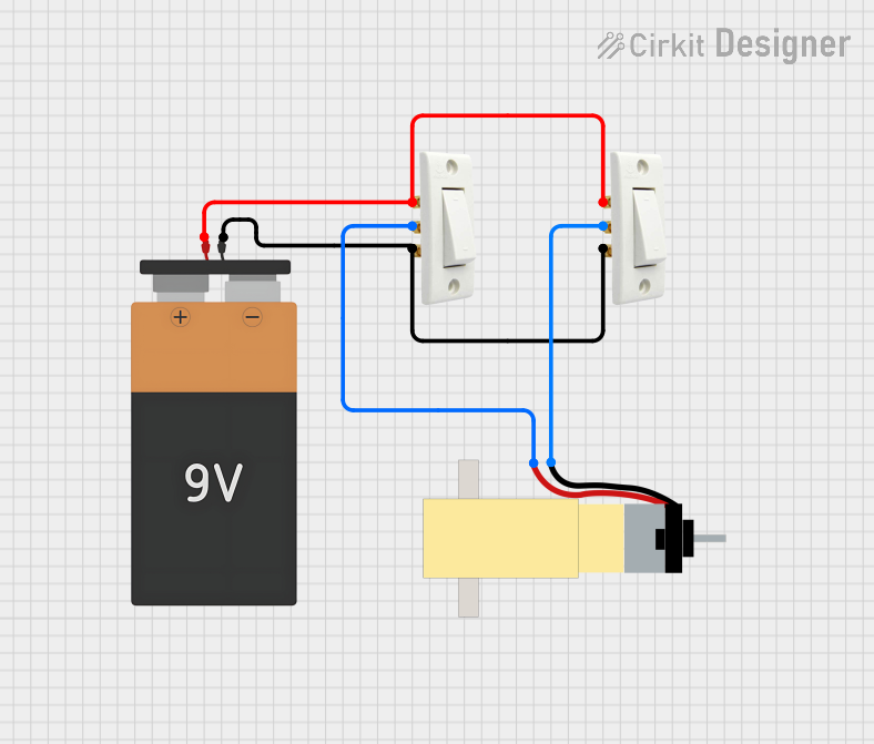 Open Project in Cirkit Designer
Explore Projects Built with SWITCH-MOMENTARY-2
Open Project in Cirkit DesignerOpen Project in Cirkit DesignerOpen Project in Cirkit DesignerOpen Project in Cirkit DesignerCommon Applications
- Reset buttons in electronic devices
- Triggering events in microcontroller-based projects
- Activating relays or other temporary circuits
- User input in control panels or keypads
- Testing and debugging circuits
Technical Specifications
The SWITCH-MOMENTARY-2 is a single-pole, single-throw (SPST) switch that operates momentarily when pressed. Below are its key technical details:
| Parameter | Specification |
|---|---|
| Operating Voltage | 3V to 24V DC |
| Maximum Current Rating | 50mA |
| Contact Resistance | ≤ 50 mΩ |
| Insulation Resistance | ≥ 100 MΩ at 500V DC |
| Operating Force | 160 ± 50 gf |
| Mechanical Life | 100,000 cycles |
| Operating Temperature | -20°C to +70°C |
| Dimensions | 6mm x 6mm x 5mm |
Pin Configuration
The SWITCH-MOMENTARY-2 typically has two pins, as shown below:
| Pin | Description |
|---|---|
| Pin 1 | Connected to one side of the circuit |
| Pin 2 | Connected to the other side of the circuit |
When the switch is pressed, the two pins are electrically connected, allowing current to flow through the circuit.
Usage Instructions
How to Use the SWITCH-MOMENTARY-2 in a Circuit
- Identify the Pins: Locate the two pins of the switch. These are not polarized, so they can be connected in either orientation.
- Connect to the Circuit:
- Connect one pin to the positive side of the circuit (e.g., a power source or signal input).
- Connect the other pin to the load or the ground, depending on the circuit design.
- Test the Switch: Press the switch to close the circuit and observe the desired action (e.g., turning on an LED or sending a signal to a microcontroller).
Important Considerations
- Debouncing: Momentary switches can produce electrical noise or "bouncing" when pressed. Use a capacitor or software-based debouncing techniques to ensure stable operation.
- Current Limiting: Ensure the current through the switch does not exceed its maximum rating (50mA). Use a resistor if necessary.
- Mounting: Secure the switch properly to avoid mechanical stress that could damage the pins or housing.
Example: Connecting to an Arduino UNO
The SWITCH-MOMENTARY-2 can be easily interfaced with an Arduino UNO for user input. Below is an example circuit and code:
Circuit Diagram
- Connect one pin of the switch to Arduino digital pin 2.
- Connect the other pin to the ground (GND).
- Use a pull-up resistor (10kΩ) between digital pin 2 and 5V to ensure a stable HIGH signal when the switch is not pressed.
Arduino Code
// Define the pin connected to the momentary switch
const int switchPin = 2;

// Variable to store the switch state
int switchState = 0;

void setup() {
  // Set the switch pin as input with an internal pull-up resistor
  pinMode(switchPin, INPUT_PULLUP);

  // Initialize serial communication for debugging
  Serial.begin(9600);
}

void loop() {
  // Read the state of the switch (LOW when pressed, HIGH when not pressed)
  switchState = digitalRead(switchPin);

  // Print the switch state to the Serial Monitor
  if (switchState == LOW) {
    Serial.println("Switch Pressed");
  } else {
    Serial.println("Switch Released");
  }

  // Add a small delay to avoid spamming the Serial Monitor
  delay(100);
}
Troubleshooting and FAQs
Common Issues
Switch Not Responding
- Cause: Poor connection or incorrect wiring.
- Solution: Check the connections and ensure the switch pins are properly soldered or inserted into the circuit.
Switch Bouncing
- Cause: Electrical noise when the switch is pressed or released.
- Solution: Add a 0.1µF capacitor across the switch pins or implement software debouncing in your code.
Exceeding Current Rating
- Cause: The load connected to the switch draws more than 50mA.
- Solution: Use a transistor or relay to handle higher currents.
Switch Feels Stiff or Unresponsive
- Cause: Mechanical wear or debris inside the switch.
- Solution: Replace the switch if it has exceeded its mechanical life or clean it carefully if possible.
FAQs
Q: Can I use the SWITCH-MOMENTARY-2 for AC circuits?
A: No, this switch is designed for low-voltage DC circuits only. Using it in AC circuits may damage the switch or pose a safety hazard.
Q: How do I debounce the switch in software?
A: You can use a simple delay or a state-change detection algorithm in your code to filter out bouncing signals.
Q: Can I use this switch to directly control a motor?
A: No, the switch cannot handle high currents required by motors. Use a relay or transistor to control the motor instead.
Q: What happens if I connect the pins in reverse?
A: The switch is non-polarized, so the pins can be connected in either orientation without any issues.