How to Use Omron CP2E-N40DT-A: Examples, Pinouts, and Specs
Introduction
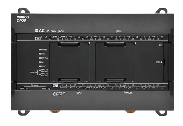
The Omron CP2E-N40DT-A is a compact and versatile programmable logic controller (PLC) designed for industrial automation applications. With 40 I/O points, built-in Ethernet communication, and support for multiple programming languages, this PLC is ideal for small to medium-sized control systems. Its compact design and robust functionality make it suitable for applications such as machine control, process automation, and data acquisition.
Explore Projects Built with Omron CP2E-N40DT-A


Explore Projects Built with Omron CP2E-N40DT-A
Common Applications
- Industrial machinery control
- Conveyor systems
- Packaging machines
- Building automation
- Data logging and monitoring
Technical Specifications
General Specifications
| Parameter | Value |
|---|---|
| Model Number | CP2E-N40DT-A |
| Manufacturer | Omron |
| Power Supply Voltage | 24 VDC |
| Number of I/O Points | 40 (24 digital inputs, 16 digital outputs) |
| Output Type | Transistor (NPN) |
| Communication Interfaces | Ethernet, RS-232C, RS-485 |
| Programming Languages | Ladder Diagram (LD), Structured Text (ST), Function Block Diagram (FBD) |
| Operating Temperature Range | 0°C to 55°C |
| Dimensions (W x H x D) | 90 mm x 85 mm x 70 mm |
Pin Configuration and Descriptions
Digital Inputs
| Pin Number | Description | Voltage Range |
|---|---|---|
| 1-24 | Digital Input Channels | 24 VDC (sink/source) |
Digital Outputs
| Pin Number | Description | Output Type |
|---|---|---|
| 25-40 | Digital Output Channels | Transistor (NPN) |
Communication Ports
| Port Name | Description | Protocols Supported |
|---|---|---|
| Ethernet | Built-in Ethernet Port | Modbus TCP, FINS |
| RS-232C | Serial Communication Port | ASCII, Modbus RTU |
| RS-485 | Serial Communication Port | Modbus RTU |
Usage Instructions
How to Use the CP2E-N40DT-A in a Circuit
- Power Supply Connection: Connect a 24 VDC power supply to the PLC's power input terminals. Ensure proper polarity to avoid damage.
- Input Connections: Wire the digital input devices (e.g., sensors, switches) to the input terminals (1-24). Verify the voltage range is within 24 VDC.
- Output Connections: Connect the digital output devices (e.g., relays, actuators) to the output terminals (25-40). Ensure the devices are compatible with the NPN transistor outputs.
- Communication Setup: Use the Ethernet, RS-232C, or RS-485 ports to connect the PLC to other devices or networks. Configure the communication settings in the programming software.
- Programming: Use Omron's CX-Programmer or Sysmac Studio software to create and upload your control program. Select the desired programming language (LD, ST, or FBD) based on your application requirements.
Important Considerations
- Ensure the power supply voltage is stable and within the specified range (24 VDC ±10%).
- Use proper grounding to minimize electrical noise and interference.
- Avoid exceeding the maximum current ratings for the digital outputs.
- Regularly back up your PLC programs to prevent data loss.
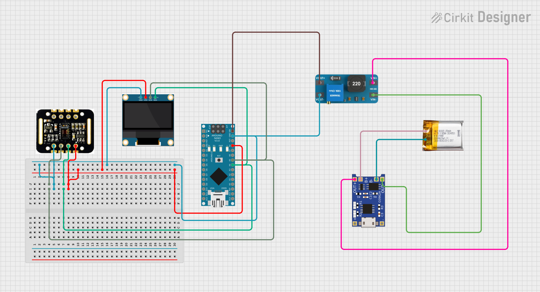
Example Code for Arduino UNO Communication
The CP2E-N40DT-A can communicate with an Arduino UNO via Modbus RTU over RS-485. Below is an example Arduino sketch for reading data from the PLC:
#include <ModbusMaster.h>

// Instantiate ModbusMaster object
ModbusMaster node;

void setup() {
  Serial.begin(9600); // Initialize serial communication
  node.begin(1, Serial); // Set Modbus slave ID to 1
}

void loop() {
  uint8_t result;
  uint16_t data;

  // Read a holding register (e.g., address 0x0001)
  result = node.readHoldingRegisters(0x0001, 1);

  if (result == node.ku8MBSuccess) {
    data = node.getResponseBuffer(0); // Retrieve the data
    Serial.print("Register Value: ");
    Serial.println(data);
  } else {
    Serial.println("Communication Error");
  }

  delay(1000); // Wait 1 second before the next request
}
Note: Use an RS-485 module (e.g., MAX485) to interface the Arduino UNO with the PLC. Ensure proper wiring and termination resistors for reliable communication.
Troubleshooting and FAQs
Common Issues and Solutions
PLC Does Not Power On
- Cause: Incorrect power supply voltage or polarity.
- Solution: Verify the power supply voltage is 24 VDC and check the wiring polarity.
Inputs Not Detected
- Cause: Faulty wiring or incompatible input devices.
- Solution: Check the wiring connections and ensure the input devices operate within the specified voltage range.
Outputs Not Functioning
- Cause: Overloaded outputs or incorrect wiring.
- Solution: Verify the output devices' current ratings and check the wiring connections.
Communication Failure
- Cause: Incorrect communication settings or wiring issues.
- Solution: Ensure the communication parameters (baud rate, parity, etc.) match between the PLC and the connected device. Check the wiring for loose connections or damage.
FAQs
Q: Can the CP2E-N40DT-A be programmed using Sysmac Studio?
A: Yes, the CP2E-N40DT-A supports programming via Sysmac Studio as well as CX-Programmer.
Q: What is the maximum cable length for RS-485 communication?
A: The maximum recommended cable length for RS-485 is 1,200 meters, depending on the baud rate and cable quality.
Q: Does the PLC support analog inputs/outputs?
A: No, the CP2E-N40DT-A does not have built-in analog I/O. However, external modules can be used for analog functionality.
Q: Can I use the PLC in high-temperature environments?
A: The operating temperature range is 0°C to 55°C. Ensure the PLC is installed in a well-ventilated area to avoid overheating.