
How to Use PCA9685 Servo Driver: Examples, Pinouts, and Specs
 Design with PCA9685 Servo Driver in Cirkit Designer
Introduction
The PCA9685 is a 16-channel, 12-bit PWM (Pulse Width Modulation) driver designed for controlling servos and LEDs. It communicates via the I2C protocol, enabling precise control of up to 16 independent PWM outputs using minimal microcontroller resources. This makes it an ideal choice for robotics, lighting systems, and other applications requiring multiple PWM signals.
Explore Projects Built with PCA9685 Servo Driver
 Open Project in Cirkit Designer
 Open Project in Cirkit Designer
 Open Project in Cirkit Designer
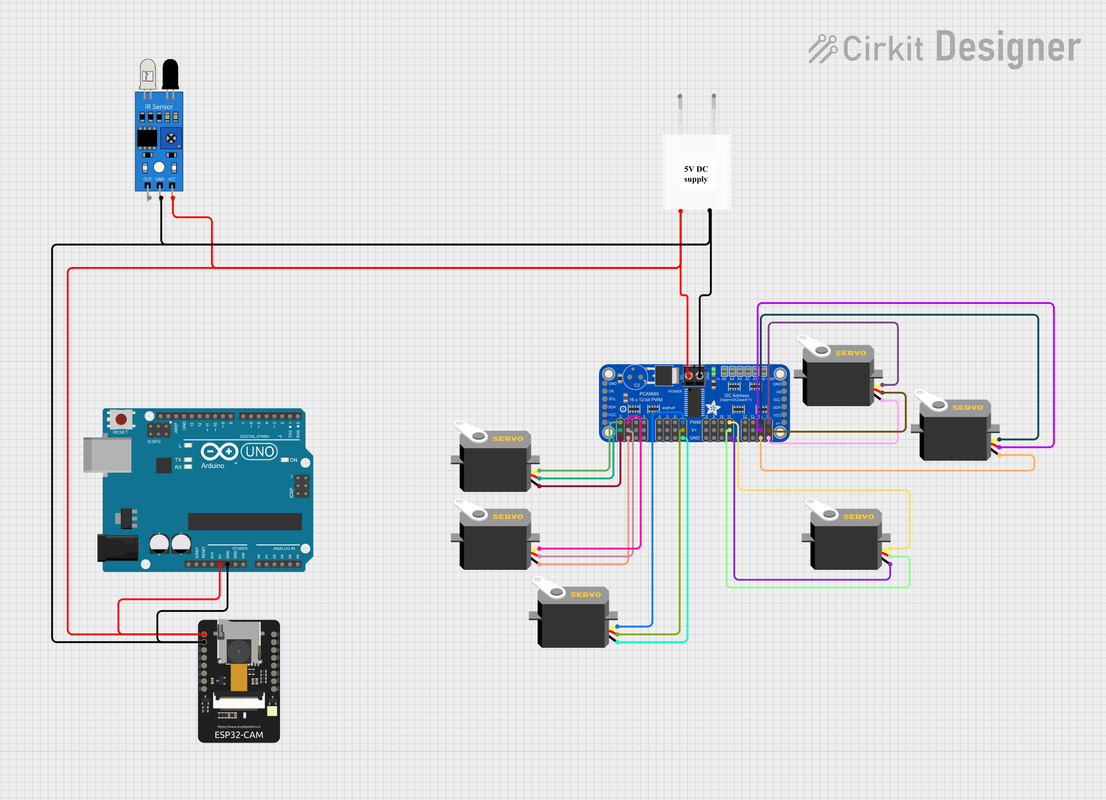 Open Project in Cirkit Designer
Explore Projects Built with PCA9685 Servo Driver
Open Project in Cirkit DesignerOpen Project in Cirkit DesignerOpen Project in Cirkit DesignerOpen Project in Cirkit DesignerCommon Applications and Use Cases
- Controlling servo motors in robotics and automation projects
- Driving LED arrays for lighting or display systems
- Generating PWM signals for motor speed control
- Applications requiring precise timing and multi-channel PWM control
Technical Specifications
Key Technical Details
- Number of Channels: 16 independent PWM outputs
- Resolution: 12-bit (4096 steps per PWM cycle)
- Operating Voltage: 2.3V to 5.5V (logic level)
- Output Voltage: Up to 6V (external power supply for servos/LEDs)
- Communication Protocol: I2C (up to 1 MHz)
- I2C Address Range: Configurable via 6 address pins (up to 62 devices on the same bus)
- PWM Frequency: Adjustable from 24 Hz to 1526 Hz
- Output Current: 25 mA per channel (sink), 10 mA per channel (source)
- Operating Temperature: -40°C to +85°C
Pin Configuration and Descriptions
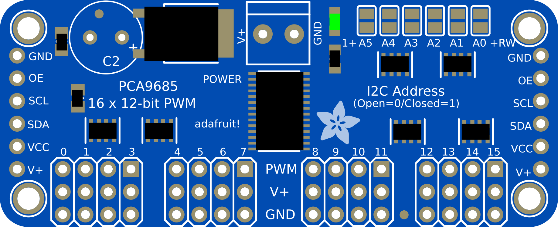
The PCA9685 is typically available in a 28-pin package. Below is the pin configuration:
| Pin | Name | Description |
|---|---|---|
| 1-16 | PWM0-PWM15 | 16 PWM output channels for driving servos or LEDs |
| 17 | VCC | Logic voltage supply (2.3V to 5.5V) |
| 18 | GND | Ground connection |
| 19 | OE | Output enable (active low, can be used to disable all outputs) |
| 20 | SDA | I2C data line |
| 21 | SCL | I2C clock line |
| 22-27 | A0-A5 | Address pins for configuring the I2C address |
| 28 | V+ | External power supply for servos/LEDs (up to 6V) |
Usage Instructions
How to Use the PCA9685 in a Circuit
Power Connections:
- Connect the VCC pin to the logic voltage of your microcontroller (e.g., 3.3V or 5V).
- Connect the GND pin to the ground of your circuit.
- If driving servos or LEDs, connect an external power supply (up to 6V) to the V+ pin.
I2C Communication:
- Connect the SDA and SCL pins to the corresponding I2C pins on your microcontroller.
- Configure the I2C address using the A0-A5 pins if multiple PCA9685 modules are used.
PWM Output:
- Connect servos or LEDs to the PWM0-PWM15 pins.
- Ensure the external power supply (V+) matches the voltage requirements of your servos/LEDs.
Set the PWM Frequency:
- Use the I2C interface to configure the PWM frequency (e.g., 50 Hz for servos).
Control PWM Duty Cycle:
- Send commands via I2C to set the ON and OFF times for each channel.
Important Considerations and Best Practices
- Use decoupling capacitors (e.g., 0.1 µF and 10 µF) near the VCC and V+ pins to stabilize the power supply.
- Avoid exceeding the current limits of the PCA9685 outputs. Use external transistors or drivers for high-current loads.
- For servo applications, ensure the external power supply (V+) can handle the combined current draw of all connected servos.
- Keep I2C lines short and use pull-up resistors (typically 4.7 kΩ) on the SDA and SCL lines.
Example Code for Arduino UNO
Below is an example of how to use the PCA9685 with an Arduino UNO to control a servo motor:
#include <Wire.h>
#include <Adafruit_PWMServoDriver.h>

// Create an instance of the PCA9685 driver
Adafruit_PWMServoDriver pwm = Adafruit_PWMServoDriver();

#define SERVO_MIN 150 // Minimum pulse length count (adjust for your servo)
#define SERVO_MAX 600 // Maximum pulse length count (adjust for your servo)

void setup() {
  Serial.begin(9600);
  Serial.println("Initializing PCA9685...");

  pwm.begin(); // Initialize the PCA9685
  pwm.setPWMFreq(50); // Set PWM frequency to 50 Hz (common for servos)

  Serial.println("PCA9685 ready.");
}

void loop() {
  // Sweep the servo from 0 to 180 degrees
  for (int pulse = SERVO_MIN; pulse <= SERVO_MAX; pulse++) {
    pwm.setPWM(0, 0, pulse); // Channel 0, start at 0, set pulse width
    delay(10); // Small delay for smooth movement
  }

  // Sweep the servo back from 180 to 0 degrees
  for (int pulse = SERVO_MAX; pulse >= SERVO_MIN; pulse--) {
    pwm.setPWM(0, 0, pulse); // Channel 0, start at 0, set pulse width
    delay(10); // Small delay for smooth movement
  }
}
Troubleshooting and FAQs
Common Issues and Solutions
No Output on PWM Channels:
- Ensure the PCA9685 is powered correctly (check VCC and GND connections).
- Verify the I2C connections (SDA, SCL) and ensure pull-up resistors are present.
- Check the I2C address configuration (A0-A5 pins) and ensure it matches your code.
Servos Not Moving or Jittering:
- Confirm the external power supply (V+) is sufficient for the servos.
- Verify the PWM frequency is set to 50 Hz for standard servos.
- Check the pulse width values (SERVO_MIN and SERVO_MAX) and adjust them for your specific servo.
I2C Communication Errors:
- Ensure the I2C lines are not too long and have proper pull-up resistors.
- Check for address conflicts if multiple I2C devices are connected.
FAQs
Can I use the PCA9685 with 3.3V microcontrollers? Yes, the PCA9685 supports logic levels from 2.3V to 5.5V, making it compatible with 3.3V and 5V systems.
What is the maximum number of PCA9685 modules I can use on one I2C bus? Up to 62 PCA9685 modules can be connected on the same I2C bus by configuring their addresses using the A0-A5 pins.
Can the PCA9685 drive high-power LEDs directly? No, the PCA9685 outputs are limited to 25 mA per channel. Use external transistors or MOSFETs for high-power LEDs.