Cirkit Designer
Your all-in-one circuit design IDE
Home /
Component Documentation
How to Use GEMMA v1: Examples, Pinouts, and Specs
Introduction
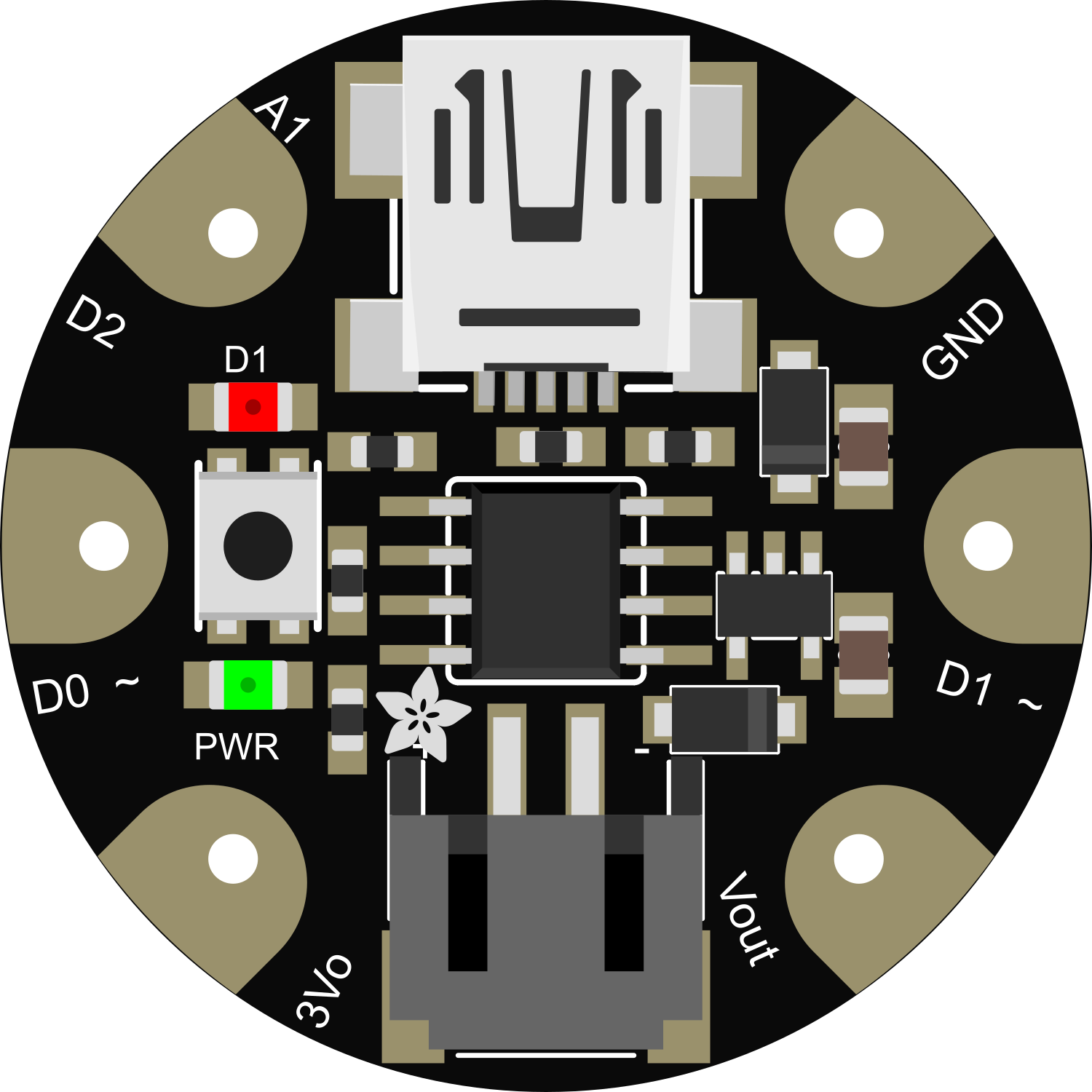
The GEMMA v1 is a miniature wearable electronic platform powered by the ATtiny85 microcontroller. It is designed by Adafruit for small-scale projects where size and power efficiency are crucial. The GEMMA v1 is ideal for wearables, e-textiles, and IoT applications due to its tiny footprint and versatile I/O options.
Explore Projects Built with GEMMA v1
ESP32-Based Voice Assistant with Battery-Powered Microphone and Speaker
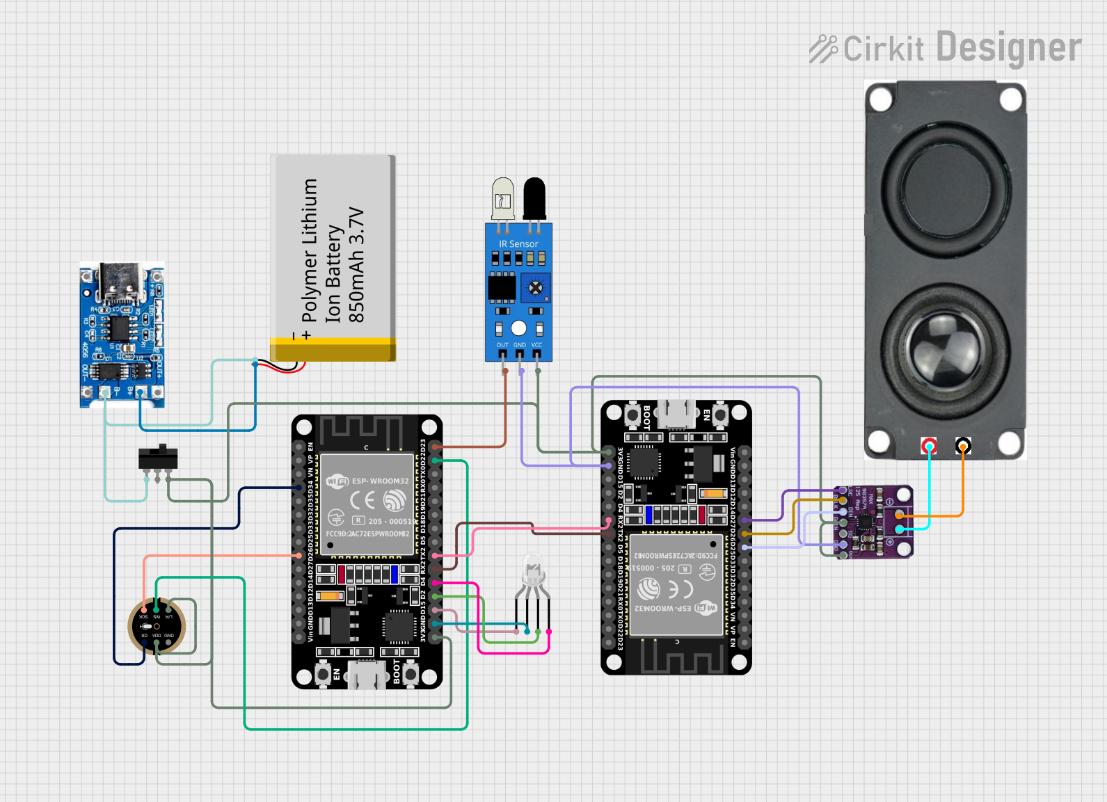
This circuit is a voice-controlled system that uses an ESP32 microcontroller to process audio input from a microphone, send the data to a Gemini API for speech-to-text conversion, and output responses through a speaker. It includes an IR sensor for additional input, an LED for status indication, and a battery with a charging module for power management.
I2C-Controlled OLED Display with External EEPROM and Interactive Pushbuttons

This is a microcontroller-based interactive device featuring a Wemos D1 Mini, an OLED display, external EEPROM, and an I/O expander. It includes user input buttons and status LEDs, with potential MIDI interface capabilities.
Arduino Mega 2560 Based Security System with Fingerprint Authentication and SMS Alerts

This circuit features an Arduino Mega 2560 microcontroller interfaced with a SIM800L GSM module, two fingerprint scanners, an I2C LCD display, an IR sensor, and a piezo buzzer. Power management is handled by a PowerBoost 1000 Basic Pad USB, a TP4056 charging module, and a Li-ion 18650 battery, with an option to use a Mini AC-DC 110V-230V to 5V 700mA module for direct power supply. The primary functionality appears to be a security system with GSM communication capabilities, biometric access control, and visual/audible feedback.
ESP32-CAM and Arduino Nano Radiation Detection System with GPS and Wi-Fi Connectivity
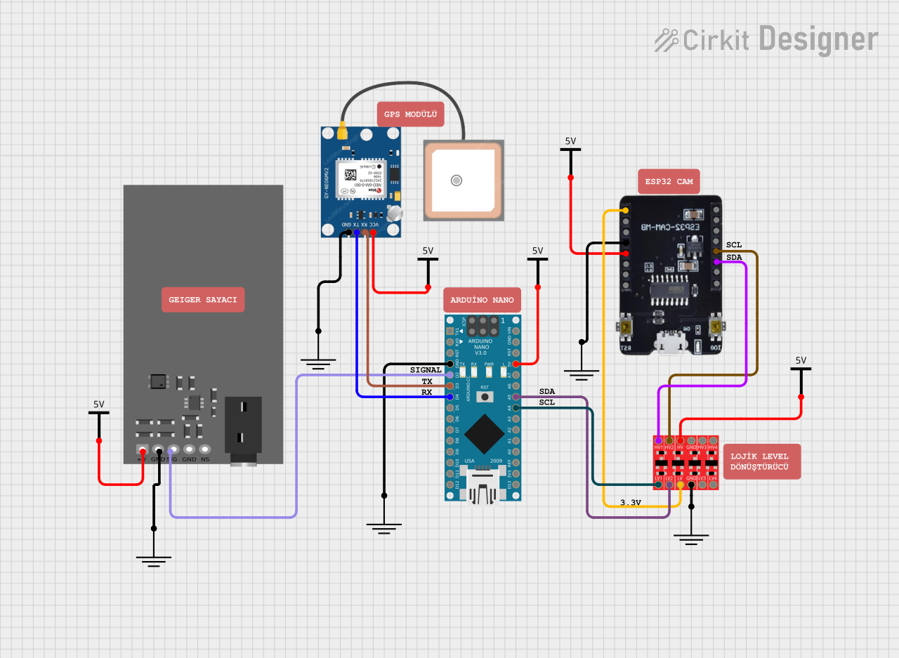
This circuit is a radiation detection and monitoring system that uses an ESP32-CAM for capturing images and streaming video, an Arduino Nano for processing data from a GPS module and a Geiger counter, and a bi-directional logic level converter for interfacing between different voltage levels. The ESP32-CAM also serves as a web server to display the radiation levels and GPS coordinates in real-time.
Explore Projects Built with GEMMA v1
ESP32-Based Voice Assistant with Battery-Powered Microphone and Speaker
This circuit is a voice-controlled system that uses an ESP32 microcontroller to process audio input from a microphone, send the data to a Gemini API for speech-to-text conversion, and output responses through a speaker. It includes an IR sensor for additional input, an LED for status indication, and a battery with a charging module for power management.
I2C-Controlled OLED Display with External EEPROM and Interactive Pushbuttons
This is a microcontroller-based interactive device featuring a Wemos D1 Mini, an OLED display, external EEPROM, and an I/O expander. It includes user input buttons and status LEDs, with potential MIDI interface capabilities.
Arduino Mega 2560 Based Security System with Fingerprint Authentication and SMS Alerts
This circuit features an Arduino Mega 2560 microcontroller interfaced with a SIM800L GSM module, two fingerprint scanners, an I2C LCD display, an IR sensor, and a piezo buzzer. Power management is handled by a PowerBoost 1000 Basic Pad USB, a TP4056 charging module, and a Li-ion 18650 battery, with an option to use a Mini AC-DC 110V-230V to 5V 700mA module for direct power supply. The primary functionality appears to be a security system with GSM communication capabilities, biometric access control, and visual/audible feedback.
ESP32-CAM and Arduino Nano Radiation Detection System with GPS and Wi-Fi Connectivity
This circuit is a radiation detection and monitoring system that uses an ESP32-CAM for capturing images and streaming video, an Arduino Nano for processing data from a GPS module and a Geiger counter, and a bi-directional logic level converter for interfacing between different voltage levels. The ESP32-CAM also serves as a web server to display the radiation levels and GPS coordinates in real-time.
Common Applications and Use Cases
- Wearable electronics (e.g., smart clothing, accessories)
- Interactive textile projects
- Small robotics
- Educational purposes for learning electronics and programming
- Prototyping IoT devices
Technical Specifications
Key Technical Details
- Microcontroller: ATtiny85
- Operating Voltage: 3.3V
- Input Voltage: 4-16V (via battery port)
- Digital I/O Pins: 3 (of which 2 are PWM capable)
- Analog Input Pins: 1 (shared with digital I/O)
- Flash Memory: 8 KB (ATtiny85) of which 2.75 KB used by bootloader
- SRAM: 512 bytes
- EEPROM: 512 bytes
- Clock Speed: 8 MHz
- Dimensions: 28mm diameter
Pin Configuration and Descriptions
| Pin Number | Name | Description |
|---|---|---|
| 1 | Vout | 3.3V output from the onboard regulator |
| 2 | A1/D2 | Analog input 1 or Digital I/O pin 2 |
| 3 | A2/D0 | Analog input 2 or Digital I/O pin 0, also PWM capable |
| 4 | A3/D1 | Analog input 3 or Digital I/O pin 1, also PWM capable |
| 5 | GND | Ground |
| 6 | BAT | Battery input for an external power source (4-16V DC) |
| 7 | 3Vo | Regulated 3.3V output, can be used to power external sensors/components |
| 8 | #RESET | Reset pin, can be used to restart the microcontroller |
Usage Instructions
How to Use the GEMMA v1 in a Circuit
Powering the GEMMA v1:
- Connect a battery to the BAT and GND pins for portable applications.
- Ensure the battery voltage is within the 4-16V range.
Programming the GEMMA v1:
- Use the USB interface and a compatible IDE (e.g., Arduino IDE) to upload sketches.
- Select the board type as "Adafruit GEMMA" in the IDE.
Connecting I/O:
- Use the digital I/O pins to connect LEDs, sensors, and other components.
- For analog input, use the A1/D2 pin.
Using PWM:
- Pins A2/D0 and A3/D1 support Pulse Width Modulation (PWM) for controlling devices like servo motors or dimming LEDs.
Important Considerations and Best Practices
- Always disconnect the battery or power source before making or altering connections.
- Be mindful of the power requirements of connected peripherals to avoid overloading the GEMMA v1.
- Use appropriate resistors when connecting LEDs to limit current and prevent damage.
- Avoid exposing the board to conductive materials that could cause shorts.
Troubleshooting and FAQs
Common Issues
GEMMA v1 not recognized by computer:
- Ensure the USB cable is properly connected and the computer's USB port is functioning.
- Try using a different USB cable or port.
Sketch upload fails:
- Check that the correct board and port are selected in the IDE.
- Press the reset button on the GEMMA v1 just before uploading.
Connected peripherals not working:
- Verify connections and ensure that the peripherals are compatible with the GEMMA v1's voltage and current specifications.
- Check for any loose connections or solder joints.
Solutions and Tips for Troubleshooting
- If the GEMMA v1 is not functioning as expected, double-check all connections and ensure that the power supply is within the specified range.
- Consult the Adafruit forums and guides for additional support and community-driven solutions.
Example Code for Arduino UNO
// Blink an LED connected to pin D1 of the GEMMA v1

#define LED_PIN 1 // Define the pin the LED is connected to

void setup() {
  pinMode(LED_PIN, OUTPUT); // Set the LED pin as an output
}

void loop() {
  digitalWrite(LED_PIN, HIGH); // Turn the LED on
  delay(1000);                // Wait for a second
  digitalWrite(LED_PIN, LOW);  // Turn the LED off
  delay(1000);                // Wait for a second
}
Note: This code is for demonstration purposes and assumes an LED with an appropriate resistor is connected to pin D1 of the GEMMA v1. Always ensure that your circuit is designed according to the component's specifications.