How to Use omron ssr g3mb-202p: Examples, Pinouts, and Specs
Introduction
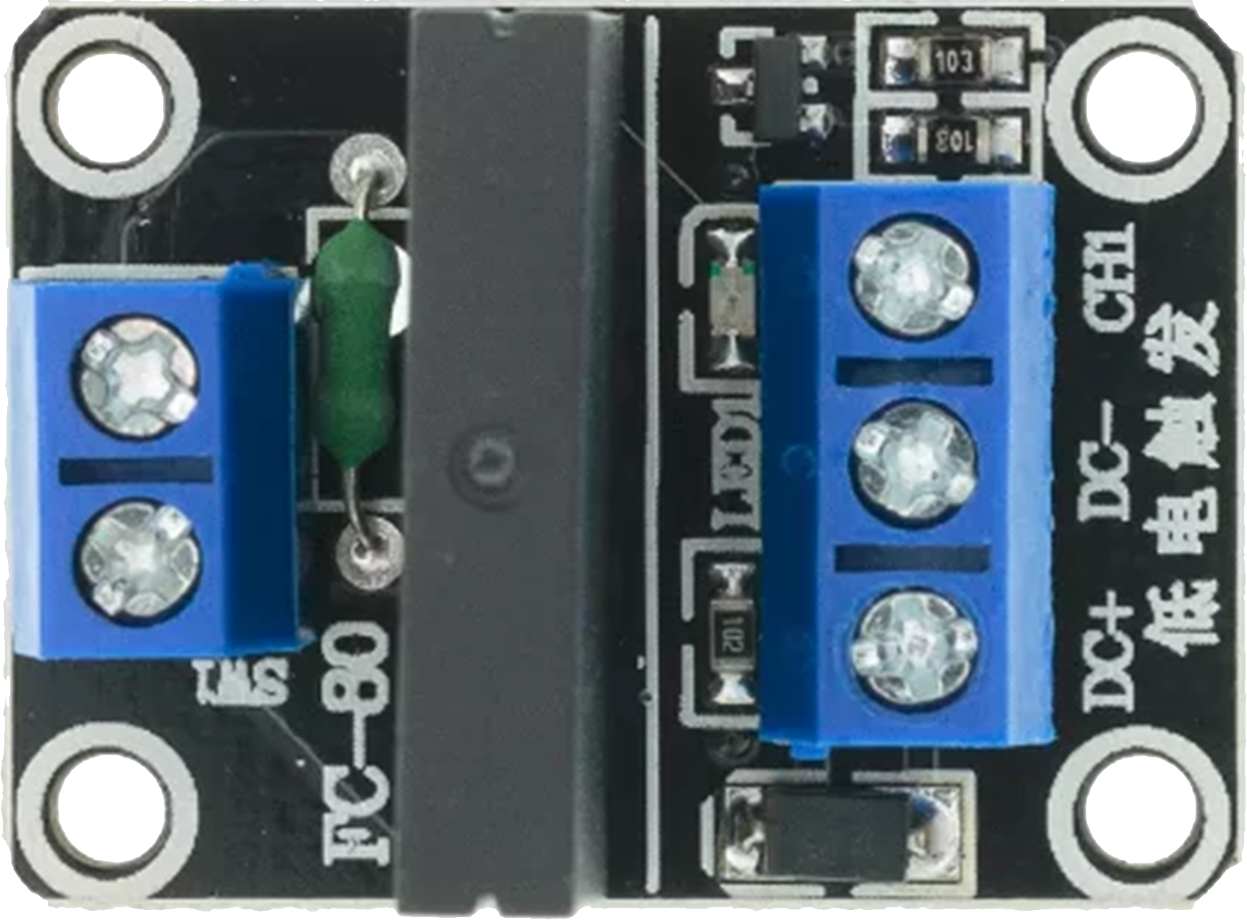
The Omron G3MB-202P Solid State Relay (SSR) is an electronic switching device that enables control of high power circuits using a low power signal. Unlike mechanical relays, SSRs use semiconductor devices to switch the load, providing silent, fast, and reliable operation. This SSR is commonly used in industrial automation, home appliances, and HVAC systems where precise control of high current loads is required with minimal electromagnetic interference (EMI).
Explore Projects Built with omron ssr g3mb-202p

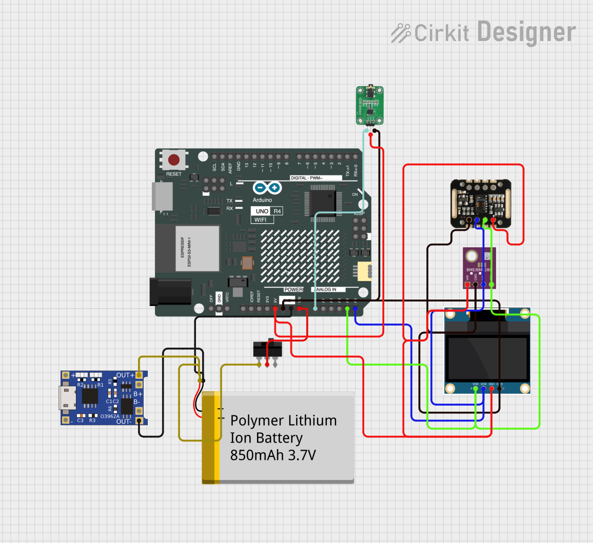
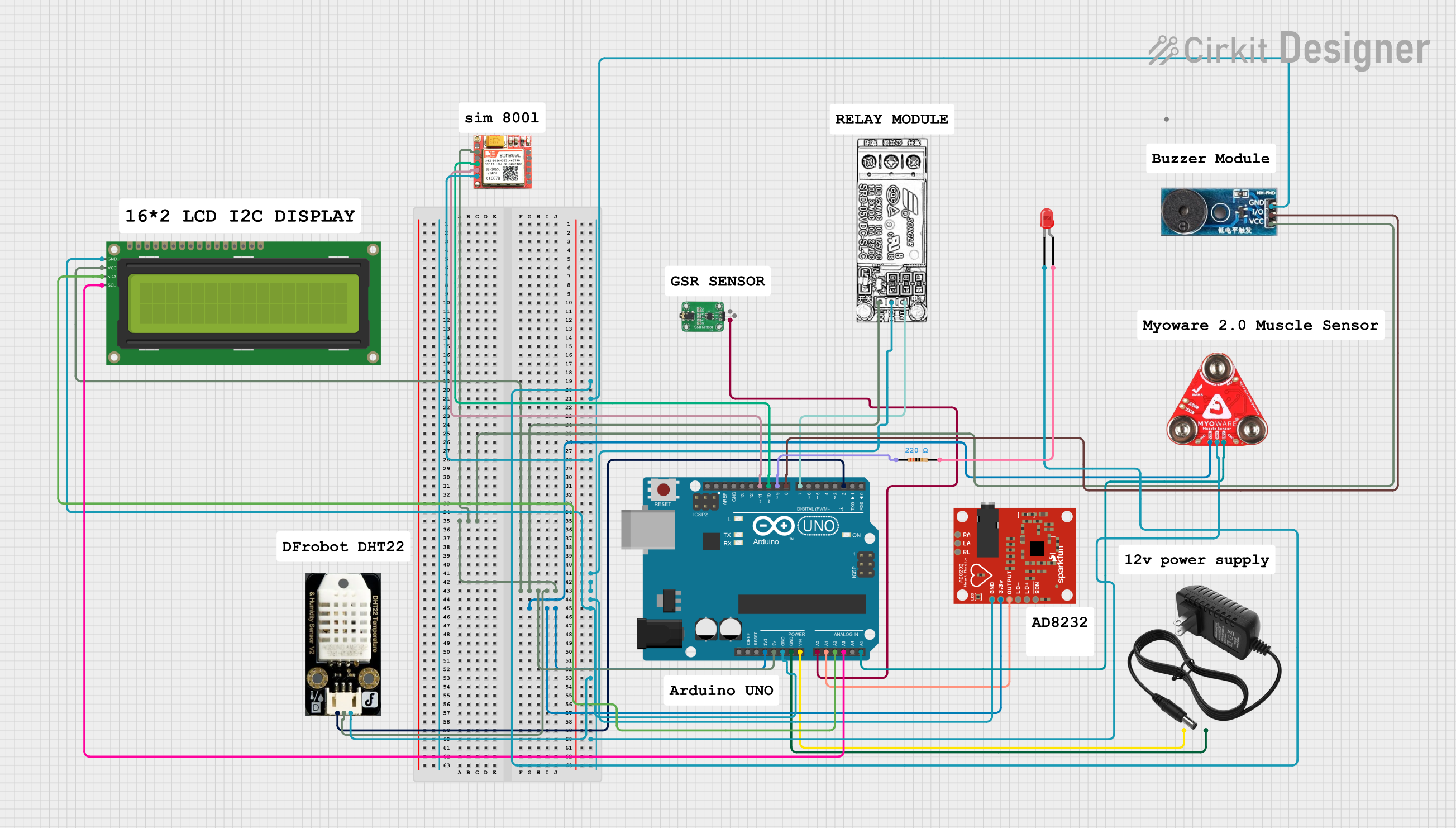

Explore Projects Built with omron ssr g3mb-202p
Technical Specifications
Key Technical Details
- Control Method: Zero Cross Trigger
- Input Voltage (Control Signal): 5VDC
- Load Voltage Range: 75 to 264 VAC
- Load Current: 2A
- Isolation Voltage: 4000VAC (between input and output)
- Operating Temperature: -30°C to 80°C
- Dimensions: 34.0 x 17.0 x 21.0 mm
Pin Configuration and Descriptions
| Pin Number | Description | Notes |
|---|---|---|
| 1 | Input Terminal (+) | Connect to positive control signal |
| 2 | Input Terminal (-) | Connect to negative control signal |
| 3 | Load Terminal (AC) | Connect to one side of the AC load |
| 4 | Load Terminal (AC) | Connect to the other side of the AC load |
Usage Instructions
How to Use the Component in a Circuit
Control Signal Connection:
- Connect the positive side of the control signal (5VDC) to Pin 1.
- Connect the negative side of the control signal to Pin 2.
Load Connection:
- Connect one side of the AC load to Pin 3.
- Connect the other side of the AC load to Pin 4.
Power Supply:
- Ensure that the control signal does not exceed 5VDC.
- The load voltage should be within the specified range of 75 to 264 VAC.
Important Considerations and Best Practices
- Heat Dissipation: SSRs can generate heat during operation. Ensure proper heat sinking or air flow to maintain optimal operating temperature.
- Surge Protection: Use surge protectors to safeguard the SSR against voltage spikes.
- Zero Cross Function: The G3MB-202P is designed to switch at the zero-cross point of the AC waveform to minimize EMI and inrush current.
- Inductive Loads: When controlling inductive loads, consider using a snubber circuit to protect against voltage spikes.
Troubleshooting and FAQs
Common Issues
- SSR Not Switching: Verify that the control signal is within the specified range and properly connected.
- Overheating: Ensure adequate heat sinking and check for overcurrent conditions.
- Load Not Powering: Check the load connections and ensure the load voltage is within the specified range.
Solutions and Tips
- Control Signal Issues: Use a multimeter to check the control signal voltage at Pins 1 and 2.
- Heat Management: Attach the SSR to a metal surface or heat sink to dissipate heat effectively.
- Load Connection: Double-check the wiring of the load to Pins 3 and 4, ensuring secure connections.
FAQs
Q: Can I use the G3MB-202P SSR with a DC load? A: No, the G3MB-202P is designed for AC loads only.
Q: What is the maximum current the G3MB-202P can handle? A: The maximum load current is 2A. Ensure the load does not exceed this rating.
Q: How do I know if the SSR is functioning properly? A: When a control signal is applied, you should be able to measure the load voltage across Pins 3 and 4. If not, the SSR may be faulty.
Example Arduino UNO Connection
// Example code to control Omron G3MB-202P SSR with an Arduino UNO

const int ssrPin = 7; // Connect to Pin 1 of SSR

void setup() {
  pinMode(ssrPin, OUTPUT); // Set the SSR pin as an output
}

void loop() {
  digitalWrite(ssrPin, HIGH); // Turn on the SSR (activate the connected AC load)
  delay(5000);                // Keep the load on for 5 seconds
  digitalWrite(ssrPin, LOW);  // Turn off the SSR (deactivate the connected AC load)
  delay(5000);                // Keep the load off for 5 seconds
}
Note: Ensure that the Arduino's ground is connected to Pin 2 of the SSR, and the digital output pin is connected to Pin 1. The SSR should be connected to an AC load as per the usage instructions. Always exercise caution when working with high voltage AC circuits.