How to Use ESP32 - Expansion Board: Examples, Pinouts, and Specs
Introduction
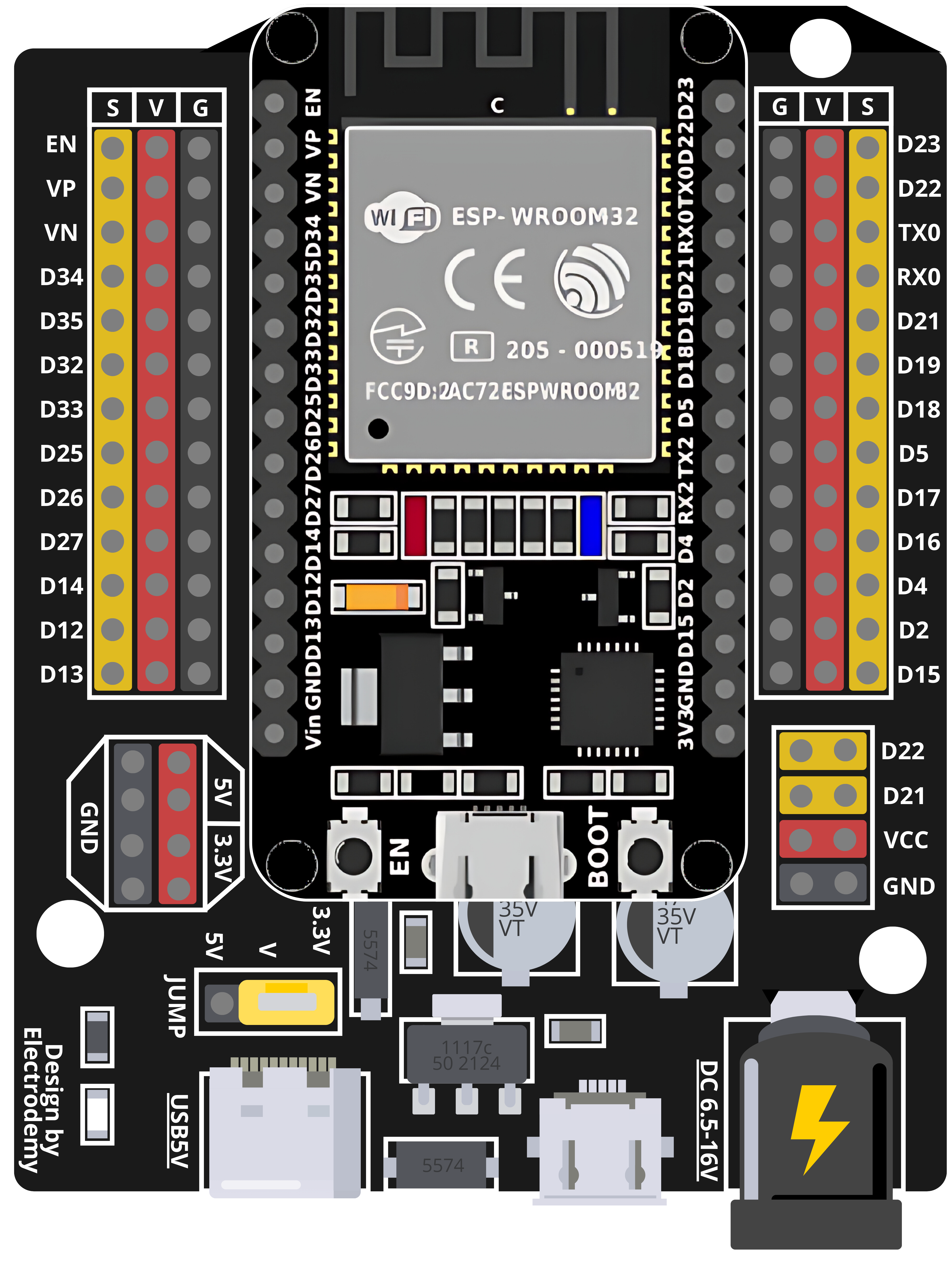
The ESP32 - Expansion Board is a versatile add-on module designed to augment the capabilities of the ESP32 microcontroller. It provides additional hardware interfaces and power management features, enabling users to connect a wide range of peripherals and sensors. Common applications include IoT devices, home automation systems, and prototyping for embedded systems.
Explore Projects Built with ESP32 - Expansion Board

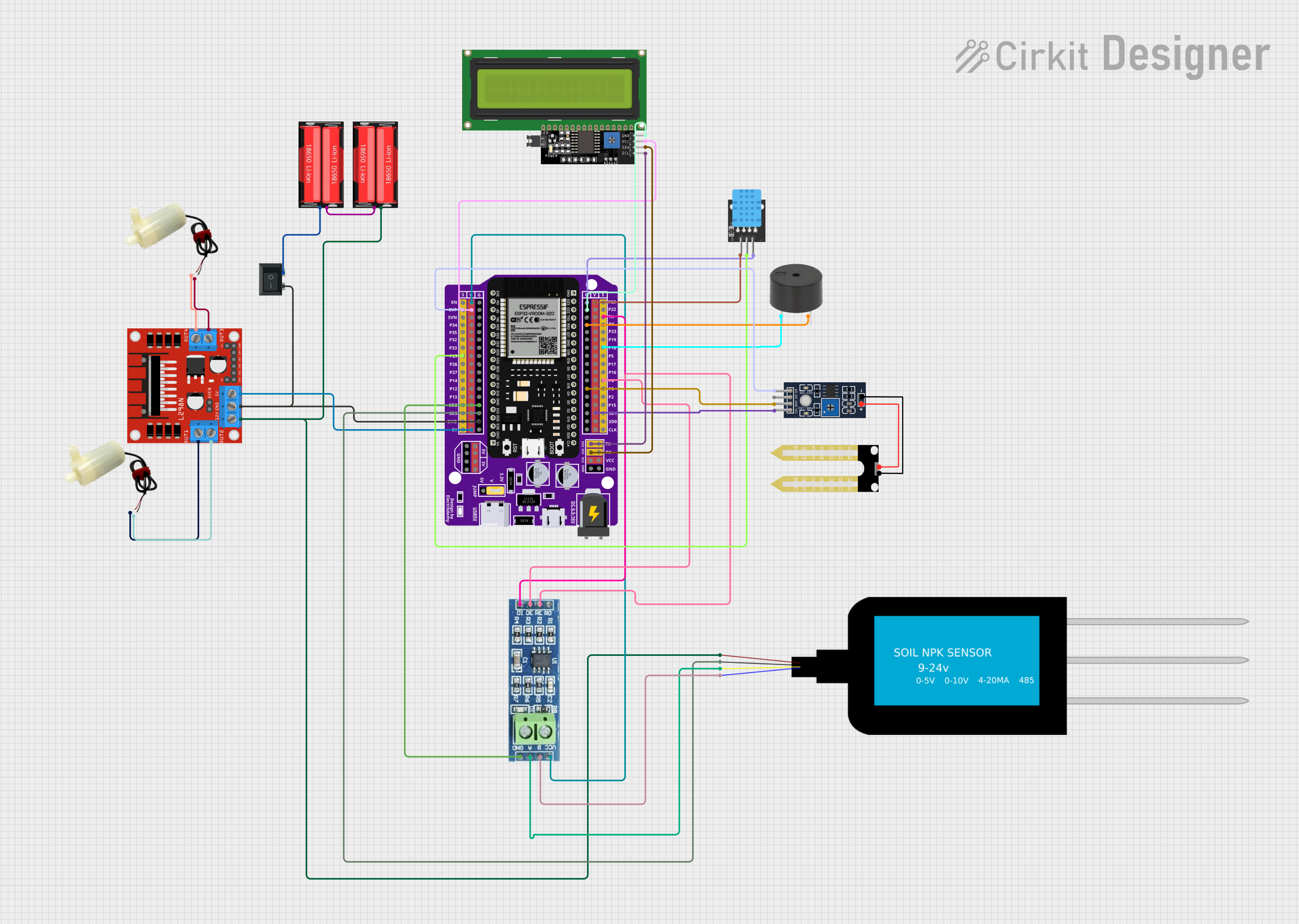
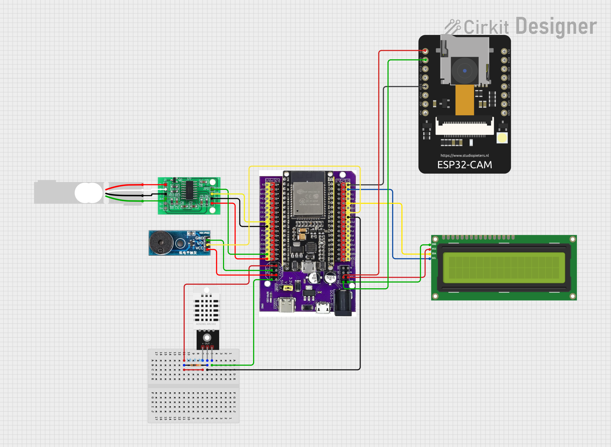
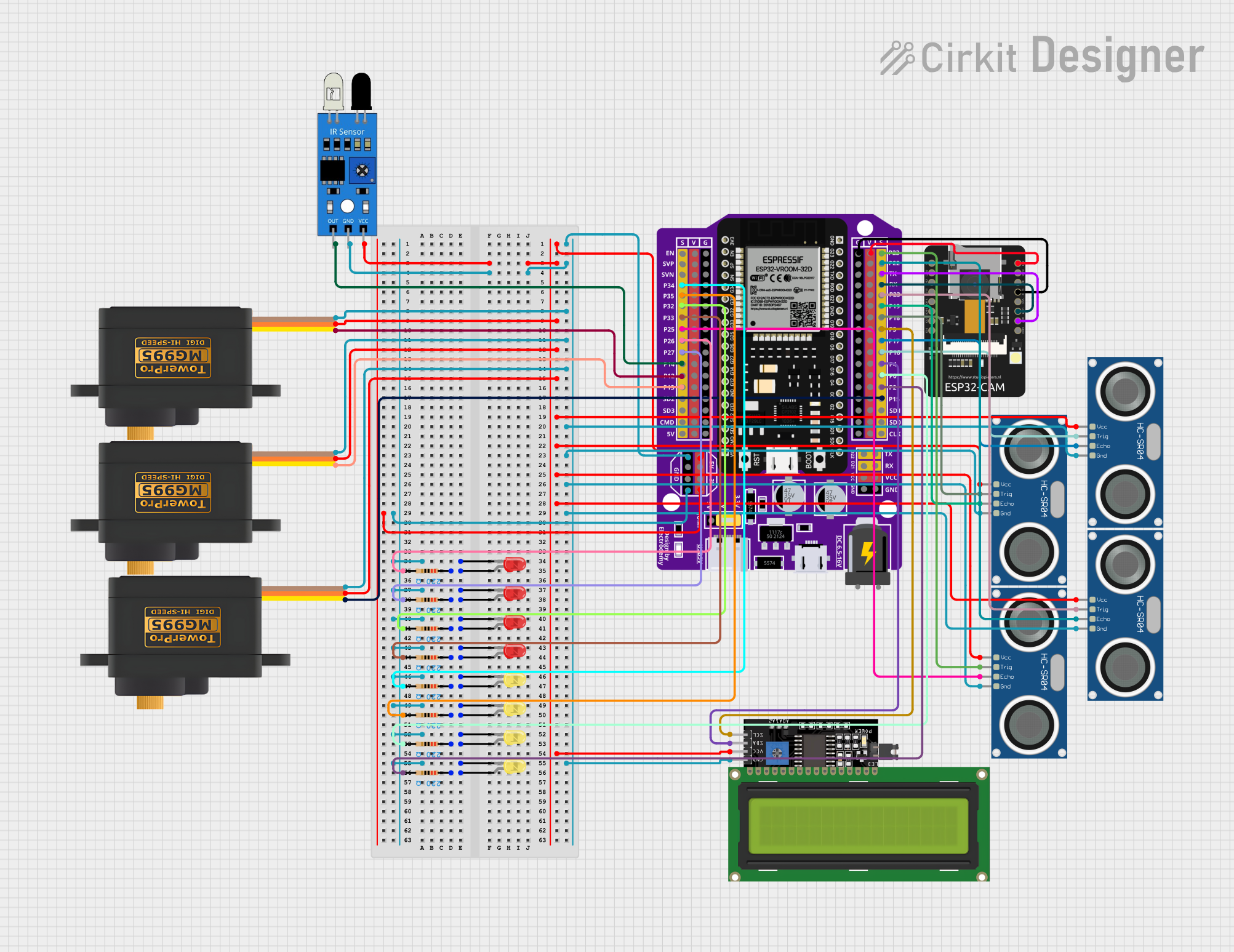
Explore Projects Built with ESP32 - Expansion Board
Technical Specifications
Key Technical Details
- Operating Voltage: 3.3V
- Input Voltage (recommended): 5V to 12V
- Input Voltage (limit): 6V to 20V
- Digital I/O Pins: 22
- Analog Input Pins: 6 (ADC channels)
- Analog Output Pins: 2 (DAC channels)
- Flash Memory: 4MB
- SRAM: 520 KB
- Clock Speed: 240 MHz
- Wi-Fi: 802.11 b/g/n
- Bluetooth: v4.2 BR/EDR and BLE
Pin Configuration and Descriptions
| Pin Number | Function | Description |
|---|---|---|
| 1 | GND | Ground |
| 2 | 3V3 | 3.3V power supply |
| 3 | EN | Reset pin (active low) |
| 4-9 | GPIO 1-6 | General-purpose input/output pins |
| 10-15 | ADC1_CH0-5 | Analog-to-digital converter 1, channels 0 to 5 |
| 16-17 | DAC1, DAC2 | Digital-to-analog converter outputs |
| 18-19 | VP, VN | ADC pre-amplifier positive and negative inputs |
| 20-21 | TX0, RX0 | UART0 transmit and receive pins |
| 22-23 | TX1, RX1 | UART1 transmit and receive pins |
| 24 | 5V | 5V power supply input |
| 25 | VIN | Raw input voltage supply for the board |
Usage Instructions
How to Use the Component in a Circuit
Powering the Board:
- Connect a 5V to 12V power supply to the VIN pin and GND.
- Alternatively, power the board via the micro-USB port.
Interfacing with Peripherals:
- Use the GPIO pins to connect sensors, actuators, or other modules.
- Analog sensors can be connected to ADC pins for reading analog values.
- Use DAC pins for analog output to devices like audio jacks or LED drivers.
Programming the ESP32:
- Connect the board to a computer using a micro-USB cable.
- Use the Arduino IDE or other compatible software to upload your code.
Important Considerations and Best Practices
- Ensure that the input voltage does not exceed the recommended limit to prevent damage.
- When using Wi-Fi or Bluetooth, place the board in a location with minimal interference.
- Use proper decoupling capacitors close to the power pins to reduce noise.
- Avoid drawing more current than the GPIO pins can handle (typically 12 mA per pin).
Troubleshooting and FAQs
Common Issues
- Board not powering up: Check the power supply and connections to VIN and GND.
- Cannot upload code: Ensure the correct drivers are installed and the board is selected in the IDE.
- Wi-Fi/Bluetooth not functioning: Verify antenna connections and check for signal interference.
Solutions and Tips
- If the board does not power up, try using a different power supply or USB cable.
- For code upload issues, double-check the USB port and board settings in the IDE.
- For wireless connectivity problems, ensure that the board's firmware is up to date.
FAQs
Q: Can I power the board using the 3V3 pin? A: It is not recommended to power the board through the 3V3 pin as it bypasses the onboard voltage regulator.
Q: How many GPIO pins can be used simultaneously? A: All 22 GPIO pins can be used, but be mindful of the total current draw.
Q: What is the maximum analog input voltage for the ADC pins? A: The maximum voltage for the ADC pins is 3.3V.
Example Code for Arduino UNO
Below is an example code snippet for blinking an LED connected to a GPIO pin on the ESP32 - Expansion Board using the Arduino IDE.
// Define the LED pin
const int ledPin = 2; // Use GPIO 2 for the LED

// Setup function runs once when you press reset or power the board
void setup() {
  // Initialize the LED pin as an output
  pinMode(ledPin, OUTPUT);
}

// Loop function runs over and over again forever
void loop() {
  digitalWrite(ledPin, HIGH);   // Turn the LED on
  delay(1000);                  // Wait for a second
  digitalWrite(ledPin, LOW);    // Turn the LED off
  delay(1000);                  // Wait for a second
}
Remember to adjust the ledPin variable to match the GPIO pin you have connected your LED to. This code will blink the LED on and off every second.