How to Use UART to ETH: Examples, Pinouts, and Specs
Introduction
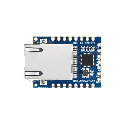
The UART to ETH module, manufactured by Waveshare (Part ID: B), is a versatile converter that bridges UART (Universal Asynchronous Receiver-Transmitter) communication with Ethernet networks. This component enables seamless transmission of serial data over Ethernet, making it ideal for applications requiring remote data access, industrial automation, IoT devices, and networked embedded systems.
By converting UART signals to Ethernet packets and vice versa, this module allows devices with serial interfaces to communicate over long distances via Ethernet infrastructure, providing flexibility and scalability in system design.
Explore Projects Built with UART to ETH


Explore Projects Built with UART to ETH
Common Applications
- Industrial automation and control systems
- IoT (Internet of Things) devices
- Remote monitoring and data logging
- Serial device networking
- Home automation systems
Technical Specifications
Key Technical Details
| Parameter | Value |
|---|---|
| Manufacturer | Waveshare |
| Part ID | B |
| Communication Protocols | UART, Ethernet |
| UART Baud Rate | 300 bps to 921.6 kbps |
| Ethernet Speed | 10/100 Mbps |
| Operating Voltage | 3.3V to 5V |
| Power Consumption | < 1W |
| Operating Temperature | -40°C to 85°C |
| Dimensions | 50mm x 30mm x 15mm |
Pin Configuration and Descriptions
The UART to ETH module has a simple pinout for easy integration into circuits. Below is the pin configuration:
| Pin Number | Pin Name | Description |
|---|---|---|
| 1 | VCC | Power input (3.3V to 5V) |
| 2 | GND | Ground |
| 3 | TXD | UART Transmit Data (output from module) |
| 4 | RXD | UART Receive Data (input to module) |
| 5 | RESET | Reset pin (active low) |
| 6 | ETH_TX+ | Ethernet transmit positive signal |
| 7 | ETH_TX- | Ethernet transmit negative signal |
| 8 | ETH_RX+ | Ethernet receive positive signal |
| 9 | ETH_RX- | Ethernet receive negative signal |
Usage Instructions
How to Use the Component in a Circuit
- Power the Module: Connect the
VCCpin to a 3.3V or 5V power source and theGNDpin to ground. - Connect UART Interface:
- Connect the
TXDpin of the module to theRXpin of your microcontroller or UART device. - Connect the
RXDpin of the module to theTXpin of your microcontroller or UART device.
- Connect the
- Connect Ethernet Interface:
- Use an Ethernet cable to connect the module to a network switch, router, or another Ethernet-enabled device.
- Configure the Module:
- Use the provided configuration software or AT commands to set the UART baud rate, IP address, and other network parameters.
- Test Communication:
- Send data from the UART device to the module and verify that it is transmitted over the Ethernet network.
Important Considerations and Best Practices
- Ensure that the UART baud rate of the module matches the baud rate of the connected device.
- Use proper grounding to avoid noise interference in UART communication.
- If using the module in a noisy environment, consider adding decoupling capacitors near the power pins.
- Configure the Ethernet settings (e.g., static IP or DHCP) according to your network requirements.
- Avoid exceeding the module's operating voltage and temperature limits to ensure reliable operation.
Example: Connecting to an Arduino UNO
Below is an example of how to connect the UART to ETH module to an Arduino UNO and send data over Ethernet.
Circuit Connections
| UART to ETH Pin | Arduino UNO Pin |
|---|---|
| VCC | 5V |
| GND | GND |
| TXD | RX (Pin 0) |
| RXD | TX (Pin 1) |
Arduino Code Example
// Example code to send data from Arduino to UART to ETH module
// Ensure the baud rate matches the module's configuration

void setup() {
  Serial.begin(9600); // Initialize UART communication at 9600 baud
  delay(1000);        // Wait for the module to initialize

  Serial.println("Hello, Ethernet!"); // Send data to the UART to ETH module
}

void loop() {
  // Continuously send data every 2 seconds
  Serial.println("Sending data over Ethernet...");
  delay(2000);
}
Troubleshooting and FAQs
Common Issues and Solutions
No Data Transmission Over Ethernet
- Cause: Incorrect UART baud rate or Ethernet configuration.
- Solution: Verify and match the UART baud rate of the module and the connected device. Check the Ethernet settings (e.g., IP address, subnet mask).
Module Not Powering On
- Cause: Insufficient power supply or incorrect voltage.
- Solution: Ensure the
VCCpin is connected to a stable 3.3V or 5V power source.
Data Corruption or Noise
- Cause: Poor grounding or long UART cables.
- Solution: Use shorter cables and ensure proper grounding. Add decoupling capacitors if necessary.
Ethernet Connection Drops Frequently
- Cause: Network instability or incorrect Ethernet wiring.
- Solution: Check the Ethernet cable and ensure proper wiring of
ETH_TX+,ETH_TX-,ETH_RX+, andETH_RX-.
FAQs
Q: Can the module work with 3.3V logic devices?
- A: Yes, the module supports both 3.3V and 5V logic levels.
Q: How do I reset the module?
- A: Pull the
RESETpin low for a few milliseconds and then release it.
- A: Pull the
Q: Can I use this module with a Raspberry Pi?
- A: Yes, connect the UART pins of the module to the GPIO UART pins of the Raspberry Pi and configure the serial port accordingly.
Q: Does the module support DHCP?
- A: Yes, the module can be configured to use DHCP or a static IP address.
This documentation provides a comprehensive guide to using the Waveshare UART to ETH module (Part ID: B). For further assistance, refer to the manufacturer's datasheet or support resources.