How to Use HerkuleX DRS-0201: Examples, Pinouts, and Specs
Introduction
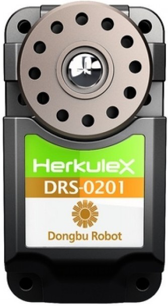
The HerkuleX DRS-0201 is a high-performance robotic servo motor designed for precise and reliable control in robotic applications. It features advanced feedback systems, including position, speed, and temperature monitoring, ensuring optimal performance and safety. With its high torque output, compact design, and versatile communication protocols, the DRS-0201 is ideal for a wide range of robotics and automation projects.
Explore Projects Built with HerkuleX DRS-0201


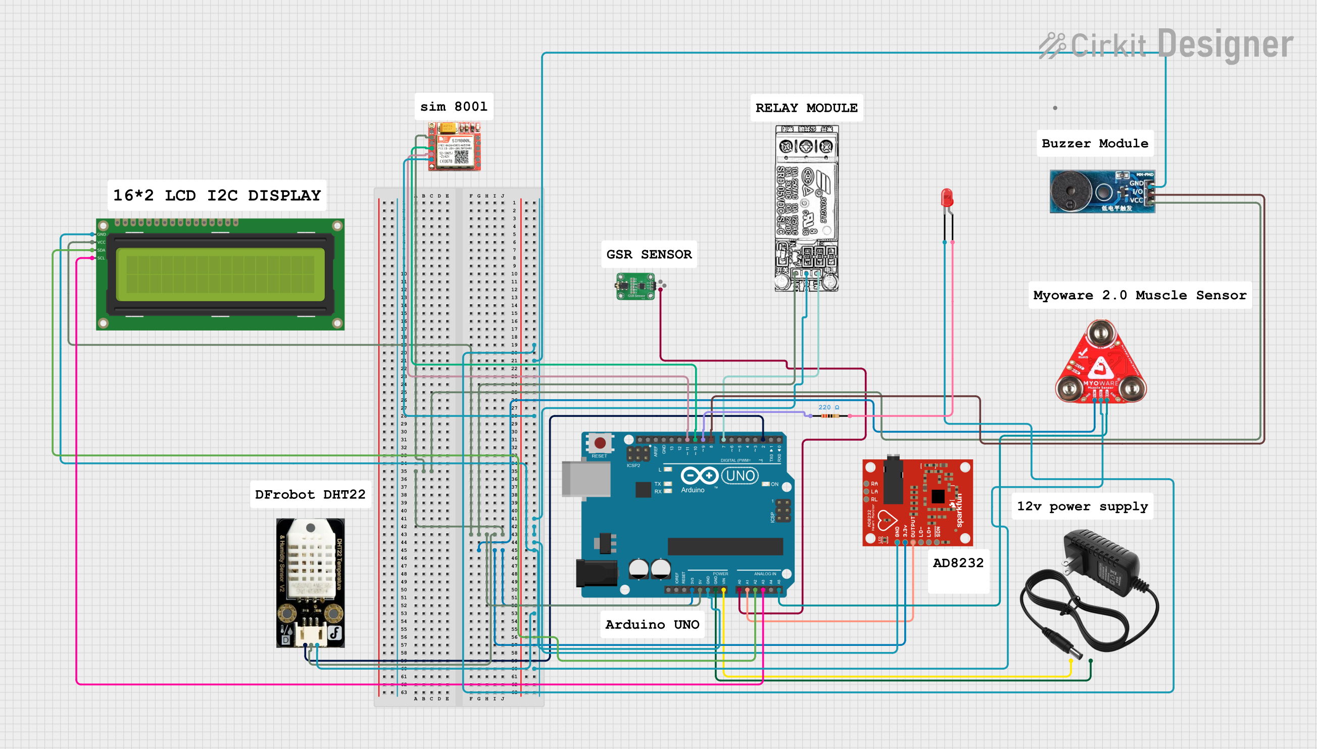
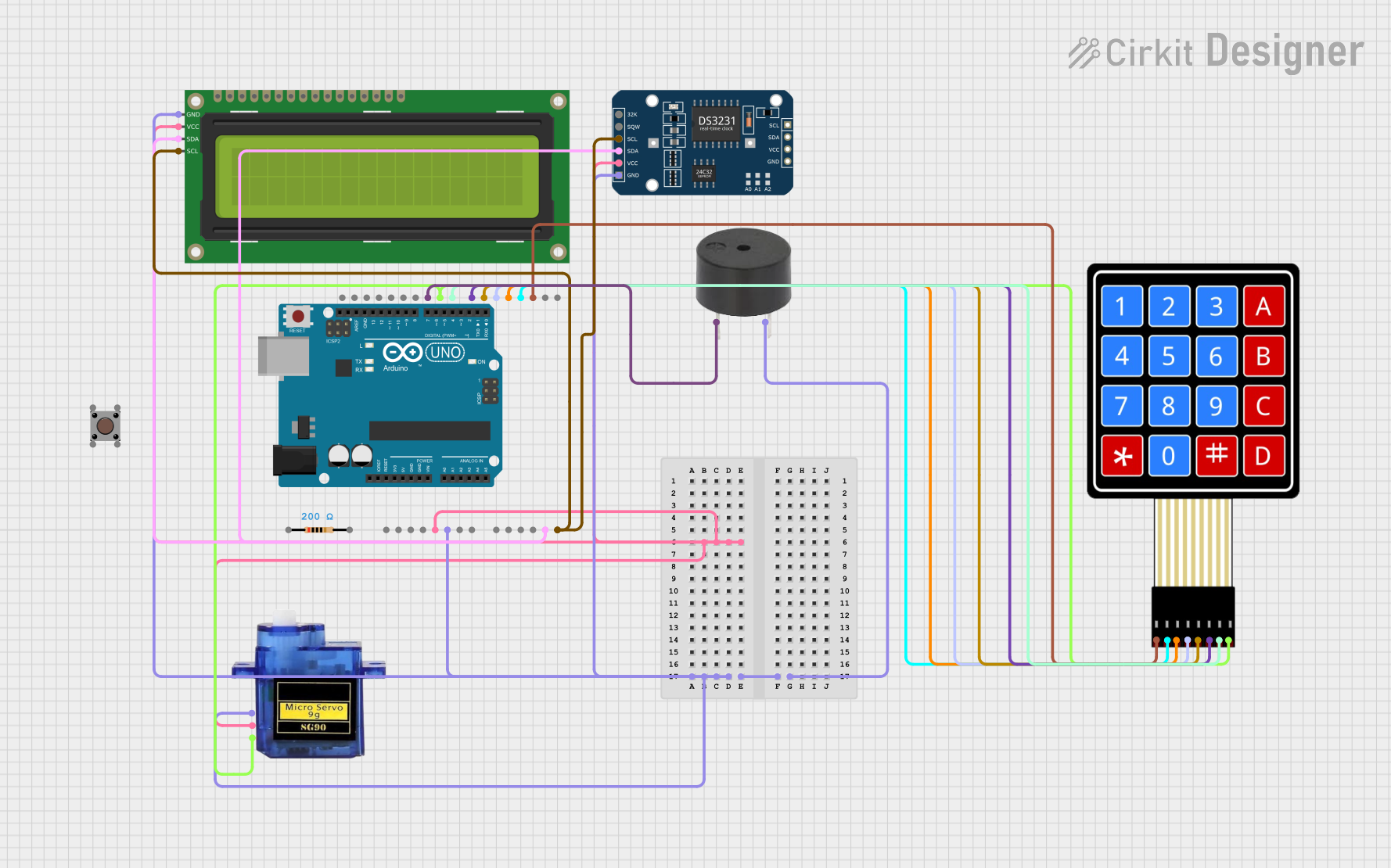
Explore Projects Built with HerkuleX DRS-0201
Common Applications and Use Cases
- Humanoid robots and robotic arms
- Autonomous vehicles and drones
- Industrial automation systems
- Educational robotics kits
- Precision control systems in research and development
Technical Specifications
Key Technical Details
| Parameter | Specification |
|---|---|
| Operating Voltage | 7.4V to 12.0V |
| Stall Torque | 24 kg·cm (at 12V) |
| No-Load Speed | 0.166 sec/60° (at 12V) |
| Communication Protocol | TTL UART (Half Duplex) |
| Feedback Features | Position, Speed, Temperature, Voltage |
| Operating Temperature | -10°C to 50°C |
| Dimensions | 40.7mm x 20mm x 37.5mm |
| Weight | 55g |
Pin Configuration and Descriptions
The HerkuleX DRS-0201 uses a 3-pin connector for power and communication. Below is the pinout:
| Pin Number | Name | Description |
|---|---|---|
| 1 | GND | Ground (0V reference) |
| 2 | VCC | Power supply (7.4V to 12.0V) |
| 3 | DATA | TTL UART communication (Half Duplex) |
Usage Instructions
How to Use the Component in a Circuit
- Power Supply: Connect the VCC pin to a regulated power source (7.4V to 12.0V) and the GND pin to the ground of your circuit.
- Communication: Use the DATA pin for TTL UART communication. Ensure that your microcontroller or control board supports half-duplex UART communication.
- Daisy-Chaining: Multiple DRS-0201 servos can be daisy-chained by connecting their DATA pins in parallel. Each servo must have a unique ID for communication.
- Initialization: Send initialization commands to the servo via UART to set its ID, baud rate, and other parameters.
Important Considerations and Best Practices
- Power Supply: Use a stable and sufficient power source to avoid voltage drops, especially when multiple servos are used.
- Heat Management: Avoid prolonged operation at high torque to prevent overheating. Monitor the temperature feedback for safety.
- Communication: Use proper termination resistors if the communication line is long or noisy.
- Mounting: Securely mount the servo to prevent vibrations or misalignment during operation.
Example Code for Arduino UNO
Below is an example of how to control the HerkuleX DRS-0201 using an Arduino UNO:
#include <SoftwareSerial.h>

// Define pins for SoftwareSerial
#define RX_PIN 10  // Arduino pin connected to the servo's DATA pin
#define TX_PIN 11  // Arduino pin connected to the servo's DATA pin

SoftwareSerial servoSerial(RX_PIN, TX_PIN); // Create a SoftwareSerial instance

void setup() {
  servoSerial.begin(115200); // Initialize UART communication at 115200 baud
  Serial.begin(9600);        // For debugging via Serial Monitor

  // Example: Set servo to position 512 (center position)
  sendServoCommand(0x01, 512); // Servo ID = 1, Position = 512
}

void loop() {
  // Add your main code here
}

// Function to send a position command to the servo
void sendServoCommand(uint8_t servoID, uint16_t position) {
  uint8_t packet[9];

  // Construct the packet
  packet[0] = 0xFF; // Header 1
  packet[1] = 0xFF; // Header 2
  packet[2] = servoID; // Servo ID
  packet[3] = 0x07; // Packet length
  packet[4] = 0x03; // Command (Move)
  packet[5] = position & 0xFF; // Position low byte
  packet[6] = (position >> 8) & 0xFF; // Position high byte
  packet[7] = calculateChecksum(packet, 7); // Checksum
  packet[8] = 0x00; // Reserved

  // Send the packet
  for (int i = 0; i < 9; i++) {
    servoSerial.write(packet[i]);
  }
}

// Function to calculate checksum
uint8_t calculateChecksum(uint8_t *packet, uint8_t length) {
  uint8_t checksum = 0;
  for (uint8_t i = 2; i < length; i++) {
    checksum ^= packet[i];
  }
  return checksum & 0xFE; // Mask the least significant bit
}
Troubleshooting and FAQs
Common Issues and Solutions
Servo Not Responding
- Cause: Incorrect wiring or power supply.
- Solution: Verify the connections and ensure the power supply is within the specified range.
Overheating
- Cause: Prolonged operation at high torque or insufficient ventilation.
- Solution: Reduce the load on the servo and ensure proper ventilation.
Communication Errors
- Cause: Incorrect baud rate or noisy communication line.
- Solution: Check the baud rate settings and use proper shielding or termination resistors.
Servo Jittering
- Cause: Unstable power supply or incorrect position commands.
- Solution: Use a stable power source and verify the position commands.
FAQs
Q: Can I use the DRS-0201 with a 5V microcontroller?
A: Yes, but you will need a level shifter to convert the 5V UART signals to the servo's TTL levels.
Q: How many servos can I daisy-chain?
A: The number depends on the power supply capacity and communication line length. Typically, up to 254 servos can be addressed.
Q: What is the default baud rate of the DRS-0201?
A: The default baud rate is 115200 bps.
Q: Can I use the DRS-0201 for continuous rotation?
A: No, the DRS-0201 is designed for precise position control, not continuous rotation.