How to Use DRV8833 Motor Driver: Examples, Pinouts, and Specs
Introduction
The DRV8833 is a dual H-bridge motor driver designed to control two DC motors or one stepper motor. It provides bidirectional control and supports adjustable speed through Pulse Width Modulation (PWM) signals. Compact and efficient, the DRV8833 is ideal for battery-powered applications due to its low standby current and wide operating voltage range. It is commonly used in robotics, automation systems, and other motor control applications.
Explore Projects Built with DRV8833 Motor Driver
Explore Projects Built with DRV8833 Motor Driver
Common Applications
- Robotics and automation
- Remote-controlled vehicles
- Conveyor belts and industrial machinery
- DIY projects involving motorized systems
- Stepper motor control for precision applications
Technical Specifications
The DRV8833 motor driver is a versatile component with the following key specifications:
| Parameter | Value |
|---|---|
| Operating Voltage Range | 2.7V to 10.8V |
| Continuous Output Current | 1A per channel (2A peak) |
| Logic Voltage Range | 1.8V to 7V |
| PWM Frequency | Up to 250 kHz |
| Standby Current | <1 µA |
| Thermal Shutdown | Yes |
| Overcurrent Protection | Yes |
| Operating Temperature | -40°C to 85°C |
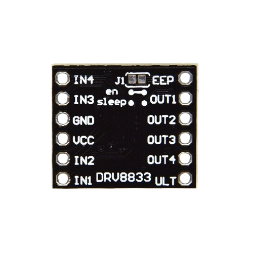
Pin Configuration and Descriptions
The DRV8833 comes in a 10-pin package. Below is the pinout and description:
| Pin | Name | Description |
|---|---|---|
| 1 | AIN1 | Input 1 for H-Bridge A. Controls motor direction when paired with AIN2. |
| 2 | AIN2 | Input 2 for H-Bridge A. Controls motor direction when paired with AIN1. |
| 3 | BIN1 | Input 1 for H-Bridge B. Controls motor direction when paired with BIN2. |
| 4 | BIN2 | Input 2 for H-Bridge B. Controls motor direction when paired with BIN1. |
| 5 | VCC | Power supply for the motor driver (2.7V to 10.8V). |
| 6 | GND | Ground connection. |
| 7 | AOUT1 | Output 1 for H-Bridge A. Connects to one terminal of Motor A. |
| 8 | AOUT2 | Output 2 for H-Bridge A. Connects to the other terminal of Motor A. |
| 9 | BOUT1 | Output 1 for H-Bridge B. Connects to one terminal of Motor B. |
| 10 | BOUT2 | Output 2 for H-Bridge B. Connects to the other terminal of Motor B. |
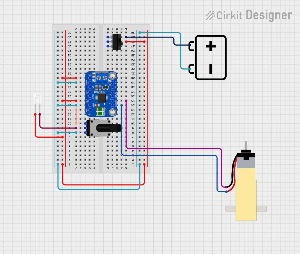
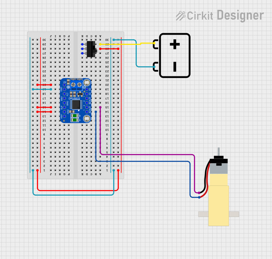
Usage Instructions
How to Use the DRV8833 in a Circuit
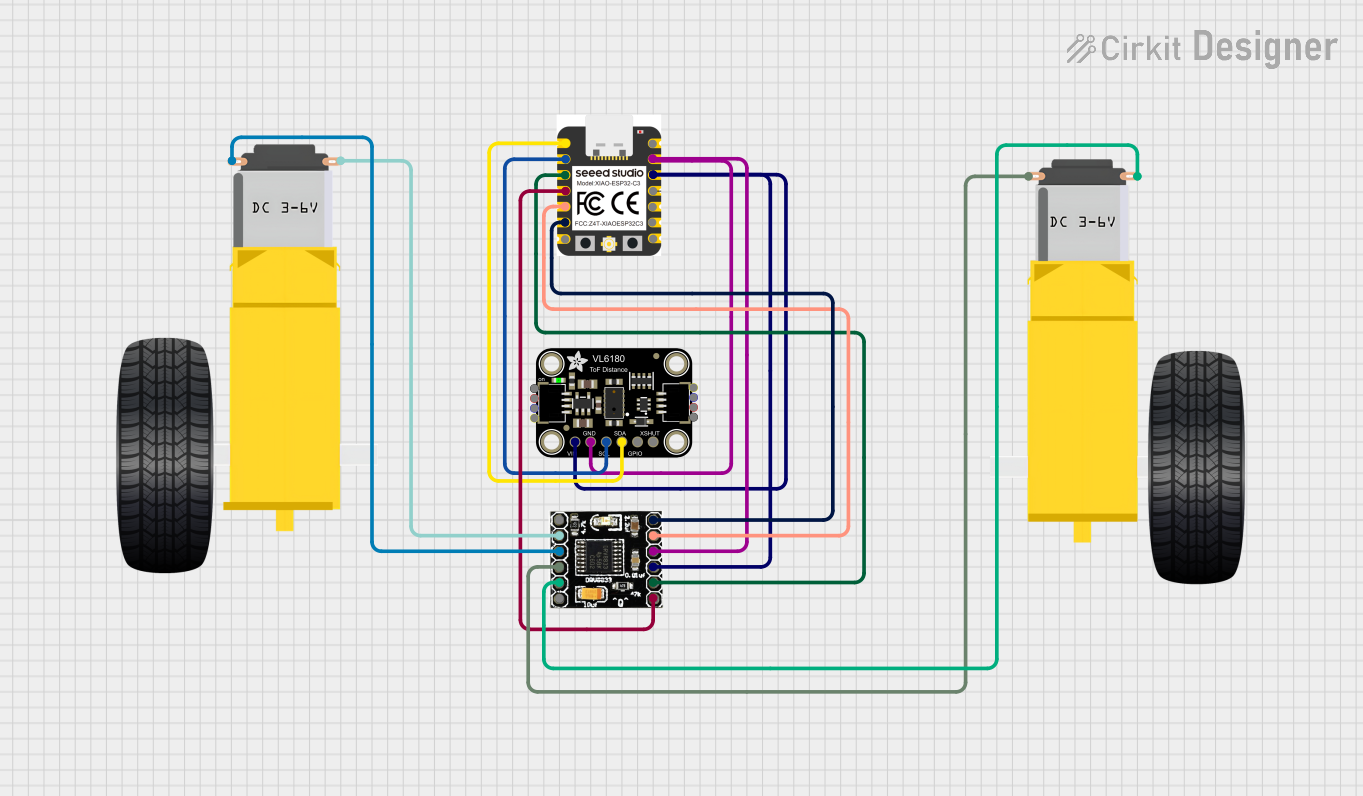
- Power Supply: Connect the VCC pin to a power source (2.7V to 10.8V) and the GND pin to ground.
- Motor Connections:
- For Motor A, connect its terminals to AOUT1 and AOUT2.
- For Motor B, connect its terminals to BOUT1 and BOUT2.
- Control Inputs:
- Use AIN1 and AIN2 to control Motor A's direction and speed.
- Use BIN1 and BIN2 to control Motor B's direction and speed.
- PWM Control: Apply PWM signals to the input pins (AIN1, AIN2, BIN1, BIN2) to adjust motor speed.
- Logic Voltage: Ensure the control signals are within the logic voltage range (1.8V to 7V).
Important Considerations and Best Practices
- Heat Dissipation: The DRV8833 can handle up to 1A per channel continuously, but ensure proper heat dissipation for higher currents.
- Decoupling Capacitors: Place a decoupling capacitor (e.g., 100 µF) near the VCC pin to stabilize the power supply.
- Protection: Avoid short circuits between motor outputs to prevent damage to the driver.
- PWM Frequency: Use a PWM frequency below 250 kHz for optimal performance.
Example: Using DRV8833 with Arduino UNO
Below is an example of controlling two DC motors using the DRV8833 and an Arduino UNO:
// Define motor control pins
const int AIN1 = 9;  // Motor A input 1
const int AIN2 = 10; // Motor A input 2
const int BIN1 = 5;  // Motor B input 1
const int BIN2 = 6;  // Motor B input 2

void setup() {
  // Set motor control pins as outputs
  pinMode(AIN1, OUTPUT);
  pinMode(AIN2, OUTPUT);
  pinMode(BIN1, OUTPUT);
  pinMode(BIN2, OUTPUT);
}

void loop() {
  // Motor A: Forward at 50% speed
  analogWrite(AIN1, 128); // PWM signal (0-255) for speed control
  digitalWrite(AIN2, LOW);

  // Motor B: Reverse at 75% speed
  digitalWrite(BIN1, LOW);
  analogWrite(BIN2, 192); // PWM signal (0-255) for speed control

  delay(2000); // Run motors for 2 seconds

  // Stop both motors
  digitalWrite(AIN1, LOW);
  digitalWrite(AIN2, LOW);
  digitalWrite(BIN1, LOW);
  digitalWrite(BIN2, LOW);

  delay(2000); // Wait for 2 seconds
}
Troubleshooting and FAQs
Common Issues and Solutions
Motors Not Running:
- Ensure the power supply voltage is within the specified range (2.7V to 10.8V).
- Verify that the control signals (AIN1, AIN2, BIN1, BIN2) are correctly configured.
- Check motor connections to the output pins (AOUT1, AOUT2, BOUT1, BOUT2).
Overheating:
- Reduce the motor load or current draw.
- Add a heatsink or improve ventilation around the DRV8833.
Erratic Motor Behavior:
- Ensure proper grounding and use decoupling capacitors to filter noise.
- Verify that the PWM frequency is below 250 kHz.
Driver Not Responding:
- Check for short circuits or incorrect wiring.
- Confirm that the logic voltage levels are within the acceptable range (1.8V to 7V).
FAQs
Q1: Can the DRV8833 drive stepper motors?
Yes, the DRV8833 can control a single bipolar stepper motor by using both H-bridges. You will need to sequence the inputs (AIN1, AIN2, BIN1, BIN2) appropriately to drive the stepper motor.
Q2: What is the maximum current the DRV8833 can handle?
The DRV8833 can handle up to 1A per channel continuously and 2A peak for short durations. Ensure proper heat dissipation for higher currents.
Q3: Can I use the DRV8833 with a 3.3V microcontroller?
Yes, the DRV8833 supports logic voltage levels as low as 1.8V, making it compatible with 3.3V microcontrollers.
Q4: Is it possible to control motor speed without PWM?
No, PWM is required to achieve variable speed control. Without PWM, the motor will operate at full speed when the input is HIGH.