How to Use Step down Buck converter: Examples, Pinouts, and Specs
Introduction
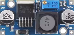
A Step Down Buck Converter is a DC-DC power converter that efficiently reduces voltage from a higher level to a lower level while simultaneously increasing the current. This type of converter is essential in applications where the supply voltage is higher than what the load requires. It is widely used in battery-operated devices, power supplies, and as a voltage regulator in various electronic circuits.
Explore Projects Built with Step down Buck converter


Explore Projects Built with Step down Buck converter
Common Applications and Use Cases
- Power regulation for embedded systems
- Battery charging circuits for lower voltage batteries
- Voltage step-down for driving LEDs
- Powering sensors or microcontrollers in a higher voltage system
Technical Specifications
Key Technical Details
- Input Voltage Range: Typically ranges from a couple of volts above the desired output to several tens of volts.
- Output Voltage Range: Usually adjustable via a potentiometer or fixed by design.
- Maximum Output Current: Depends on the specific model and cooling conditions.
- Efficiency: Generally between 80% to 95%, depending on load and input/output voltage difference.
- Switching Frequency: Varies with design, often in the range of 100 kHz to 3 MHz.
Pin Configuration and Descriptions
| Pin Number | Name | Description |
|---|---|---|
| 1 | VIN | Input voltage supply pin. Connect to the source voltage. |
| 2 | GND | Ground pin. Connect to the system ground. |
| 3 | VOUT | Output voltage pin. Provides the stepped-down voltage. |
| 4 | EN | Enable pin. A logic high enables the converter, logic low disables it. |
| 5 | FB | Feedback pin. Used for output voltage regulation, often connected to a voltage divider. |
Usage Instructions
How to Use the Component in a Circuit
- Connect the Input: Attach the source voltage to the VIN pin, ensuring it is within the specified input range for the converter.
- Grounding: Connect the GND pin to the common ground of the system.
- Output Voltage: If adjustable, set the desired output voltage using the onboard potentiometer or by setting the appropriate voltage divider on the FB pin.
- Enable the Converter: Apply a logic high signal to the EN pin to turn on the converter.
- Load Connection: Connect the load to the VOUT pin.
Important Considerations and Best Practices
- Heat Dissipation: Ensure adequate cooling for the converter, especially at high output currents.
- Input Capacitor: Place a capacitor close to the VIN pin to stabilize input power and reduce voltage spikes.
- Output Capacitor: Use an output capacitor to smooth out the output voltage and reduce noise.
- Inductor Selection: The inductor should be rated for the maximum output current and proper saturation current.
- Switching Noise: Be aware of potential electromagnetic interference (EMI) due to high-frequency switching.
Troubleshooting and FAQs
Common Issues Users Might Face
- Output Voltage Too Low or High: Check the feedback loop and adjust the potentiometer or voltage divider.
- Converter Overheating: Ensure proper heat dissipation and check if the current exceeds the maximum rating.
- Noise in the Output: Add or improve the output filtering with capacitors or inductors.
Solutions and Tips for Troubleshooting
- Inadequate Output Voltage Regulation: Verify the feedback components and connections for any faults.
- Unexpected Shutdowns: Check if the EN pin is correctly driven and if the input voltage is within the specified range.
- EMI Issues: Use proper layout techniques, shielding, and filtering to minimize interference.
FAQs
Q: Can I use the buck converter without an enable pin?
- A: Yes, if the EN pin is not required, it can be tied to VIN or left unconnected if it has an internal pull-up.
Q: What is the maximum input voltage I can apply?
- A: This depends on the specific model of the buck converter. Always refer to the datasheet for maximum ratings.
Q: How do I choose the right inductor and capacitors?
- A: Inductors and capacitors should be chosen based on the converter's switching frequency, maximum current, and desired ripple specifications.
If you are using the buck converter with an Arduino UNO, you can control the EN pin using a digital output to enable or disable the converter programmatically. Below is a simple example code snippet to control the buck converter:
// Define the enable pin for the buck converter
const int buckConverterEnablePin = 7;

void setup() {
  // Set the enable pin as an output
  pinMode(buckConverterEnablePin, OUTPUT);
}

void loop() {
  // Enable the buck converter
  digitalWrite(buckConverterEnablePin, HIGH);
  delay(5000); // Keep the converter on for 5 seconds

  // Disable the buck converter
  digitalWrite(buckConverterEnablePin, LOW);
  delay(5000); // Keep the converter off for 5 seconds
}
Remember to ensure that the logic level from the Arduino is compatible with the logic level required by the EN pin of the buck converter.