
How to Use TLP621: Examples, Pinouts, and Specs
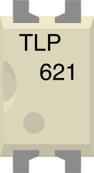
 Design with TLP621 in Cirkit Designer
Introduction
The TLP621, manufactured by Toshiba, is an optoisolator (also referred to as an optocoupler) designed to provide electrical isolation between its input and output. It consists of a gallium arsenide infrared LED on the input side and a phototransistor on the output side. This component is widely used in applications where signal isolation is required, such as interfacing between different voltage levels, protecting sensitive components from high voltages, or eliminating ground loops in circuits.
Explore Projects Built with TLP621
 Open Project in Cirkit Designer
 Open Project in Cirkit Designer
 Open Project in Cirkit Designer
 Open Project in Cirkit Designer
Explore Projects Built with TLP621
Open Project in Cirkit DesignerOpen Project in Cirkit DesignerOpen Project in Cirkit DesignerOpen Project in Cirkit DesignerCommon Applications
- Microcontroller interfacing with high-voltage circuits
- Signal isolation in industrial control systems
- Switching power supplies
- Motor control circuits
- Communication systems to prevent noise interference
Technical Specifications
Key Technical Details
| Parameter | Value |
|---|---|
| Manufacturer | Toshiba |
| Part Number | TLP621 |
| Input Type | Infrared LED |
| Output Type | Phototransistor |
| Isolation Voltage | 5000 Vrms (minimum) |
| Forward Voltage (LED) | 1.2V (typical), 1.4V (maximum) |
| Forward Current (LED) | 10mA (typical), 50mA (maximum) |
| Collector-Emitter Voltage | 55V (maximum) |
| Current Transfer Ratio (CTR) | 50% to 600% (depending on model) |
| Operating Temperature Range | -55°C to +110°C |
| Package Type | 4-pin DIP or SMD |
Pin Configuration and Descriptions
The TLP621 is available in a 4-pin DIP package. The pinout is as follows:
| Pin Number | Name | Description |
|---|---|---|
| 1 | Anode (A) | Positive terminal of the infrared LED |
| 2 | Cathode (K) | Negative terminal of the infrared LED |
| 3 | Emitter (E) | Emitter terminal of the phototransistor |
| 4 | Collector (C) | Collector terminal of the phototransistor |
Usage Instructions
How to Use the TLP621 in a Circuit
Input Side (LED):
- Connect the anode (Pin 1) to a current-limiting resistor and then to the positive voltage source.
- Connect the cathode (Pin 2) to ground.
- Ensure the forward current through the LED does not exceed 50mA. A typical forward current of 10mA is recommended for reliable operation.
Output Side (Phototransistor):
- Connect the collector (Pin 4) to the positive voltage supply through a pull-up resistor.
- Connect the emitter (Pin 3) to ground.
- The value of the pull-up resistor depends on the desired output current and voltage levels. A typical value is 10kΩ.
Isolation:
- Ensure that the input and output sides are electrically isolated to maintain the optoisolator's functionality.
Example Circuit with Arduino UNO
The following example demonstrates how to use the TLP621 to isolate a digital signal from an Arduino UNO.
Circuit Diagram
- Connect the TLP621's LED side to an Arduino digital pin with a current-limiting resistor.
- Use the phototransistor side to control an external circuit.
Arduino Code
// Example code to control the TLP621 optoisolator with Arduino UNO

const int ledPin = 9; // Arduino pin connected to the TLP621 anode
const int resistorValue = 220; // Current-limiting resistor value in ohms

void setup() {
  pinMode(ledPin, OUTPUT); // Set the pin as an output
}

void loop() {
  digitalWrite(ledPin, HIGH); // Turn on the LED in the TLP621
  delay(1000); // Wait for 1 second
  digitalWrite(ledPin, LOW); // Turn off the LED in the TLP621
  delay(1000); // Wait for 1 second
}
Important Considerations
- Current Limiting: Always use a resistor in series with the LED to limit the current and prevent damage.
- Voltage Ratings: Ensure the voltage across the phototransistor does not exceed its maximum rating of 55V.
- Isolation: Maintain proper isolation between the input and output sides to avoid compromising the optoisolator's performance.
- CTR Variations: The current transfer ratio (CTR) can vary between devices. Select a TLP621 variant with a CTR suitable for your application.
Troubleshooting and FAQs
Common Issues and Solutions
LED Not Lighting Up:
- Check the polarity of the LED connections (anode and cathode).
- Verify that the current-limiting resistor is of the correct value.
- Ensure the input voltage is sufficient to forward bias the LED.
No Output Signal:
- Confirm that the phototransistor is correctly connected (collector and emitter).
- Check the pull-up resistor value on the output side.
- Verify that the input LED is functioning and emitting light.
Signal Distortion or Noise:
- Use proper decoupling capacitors in the circuit to reduce noise.
- Ensure the input and output sides are properly isolated.
Low Current Transfer Ratio (CTR):
- Verify that the input current is within the recommended range.
- If the CTR is too low for your application, consider using a TLP621 variant with a higher CTR.
FAQs
Q: Can the TLP621 be used for AC signal isolation?
A: Yes, the TLP621 can isolate AC signals, but you will need to use a suitable circuit to drive the LED with an AC signal, such as a bridge rectifier.
Q: What is the maximum isolation voltage of the TLP621?
A: The TLP621 provides a minimum isolation voltage of 5000 Vrms, making it suitable for high-voltage isolation applications.
Q: Can the TLP621 drive a relay directly?
A: The TLP621's phototransistor output may not provide sufficient current to drive a relay directly. Use an additional transistor or driver circuit to control the relay.
Q: Is the TLP621 suitable for high-speed switching?
A: The TLP621 is not optimized for high-speed switching. For faster applications, consider using optoisolators designed for high-speed operation.
By following this documentation, you can effectively integrate the TLP621 into your electronic designs for reliable signal isolation and protection.