Cirkit Designer Logo
Cirkit Designer
Your all-in-one circuit design IDE
Home / 
Component Documentation

How to Use REF-14S: Examples, Pinouts, and Specs

Image of REF-14S
Cirkit Designer LogoDesign with REF-14S in Cirkit Designer

Introduction

The REF-14S, manufactured by RUET Electra Force, is a precision voltage reference component designed to provide a stable and accurate reference voltage in electronic circuits. This component is essential in applications where precise voltage regulation is critical, such as in analog-to-digital converters (ADCs), digital-to-analog converters (DACs), and other precision measurement systems.

Explore Projects Built with REF-14S

Use Cirkit Designer to design, explore, and prototype these projects online. Some projects support real-time simulation. Click "Open Project" to start designing instantly!
Satellite-Based Timing and Navigation System with SDR and Atomic Clock Synchronization
Image of GPS 시스템 측정 구성도_Confirm: A project utilizing REF-14S in a practical application
This circuit appears to be a complex system involving power supply management, GPS and timing synchronization, and data communication. It includes a SI-TEX G1 Satellite Compass for GPS data, an XHTF1021 Atomic Rubidium Clock for precise timing, and Ettus USRP B200 units for software-defined radio communication. Power is supplied through various SMPS units and distributed via terminal blocks and DC jacks. Data communication is facilitated by Beelink MINI S12 N95 computers, RS232 splitters, and a 1000BASE-T Media Converter for network connectivity. RF Directional Couplers are used to interface antennas with the USRP units, and the entire system is likely contained within cases for protection and organization.
Cirkit Designer LogoOpen Project in Cirkit Designer
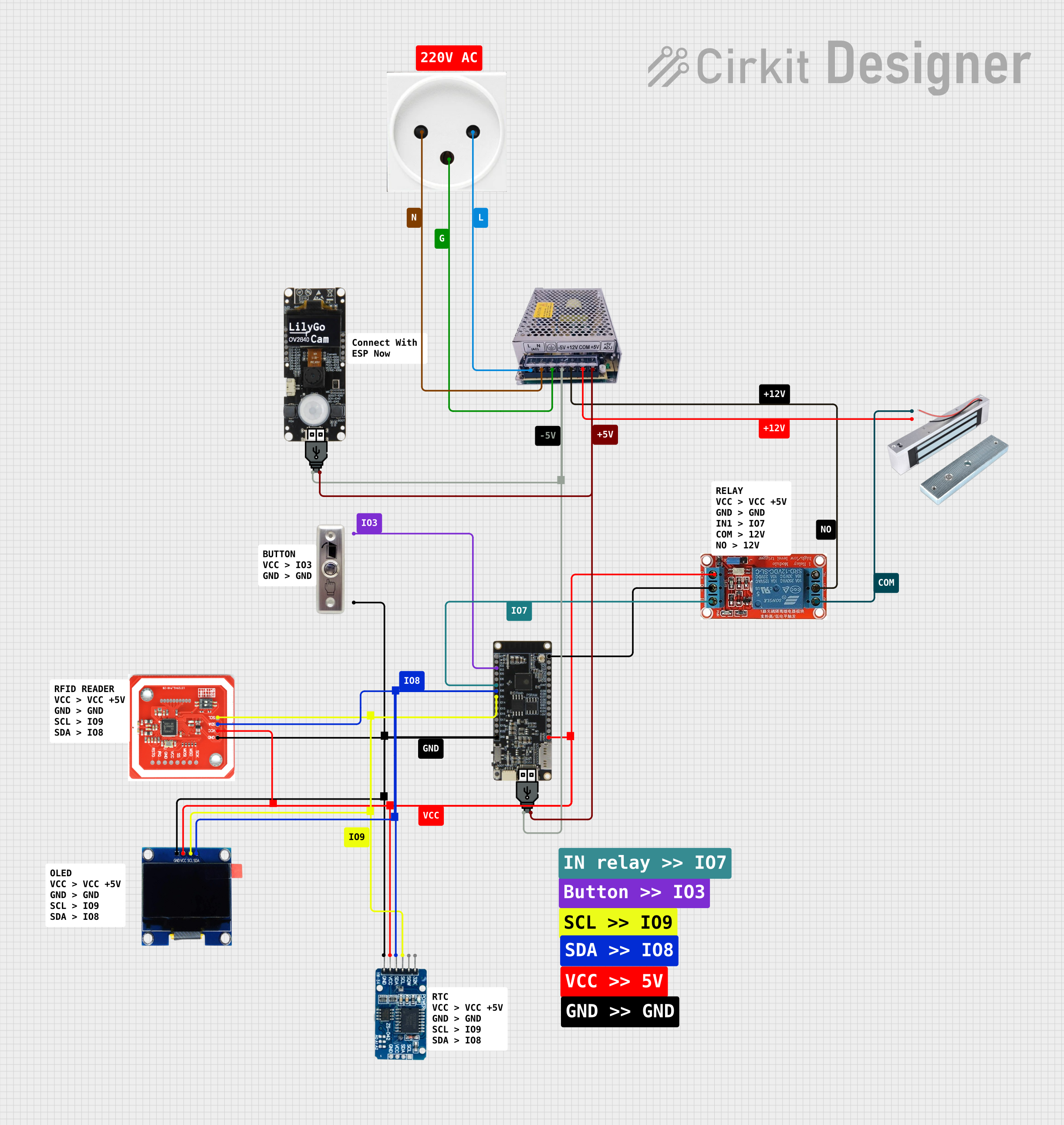
NFC-Enabled Access Control System with Time Logging
Image of doorlock: A project utilizing REF-14S in a practical application
This circuit is designed for access control with time tracking capabilities. It features an NFC/RFID reader for authentication, an RTC module (DS3231) for real-time clock functionality, and an OLED display for user interaction. A 12V relay controls a magnetic lock, which is activated upon successful NFC/RFID authentication, and a button switch is likely used for manual operation or input. The T8_S3 microcontroller serves as the central processing unit, interfacing with the NFC/RFID reader, RTC, OLED, and relay to manage the access control logic.
Cirkit Designer LogoOpen Project in Cirkit Designer
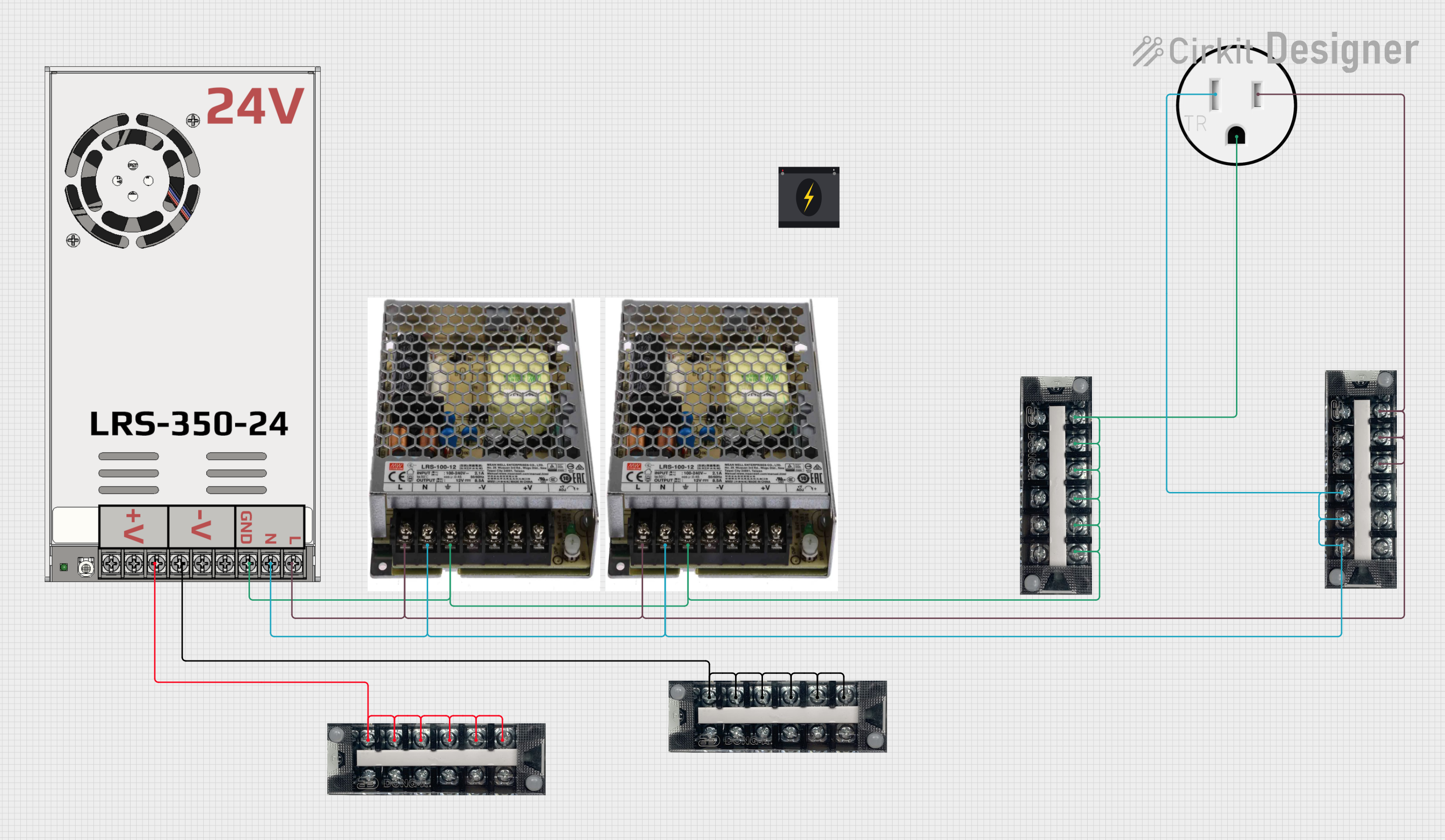
Modular Power Distribution System with Multiple SMPS Units and 120V Outlet
Image of Cellion-Tesla: A project utilizing REF-14S in a practical application
This circuit is designed to convert 240V AC power to both 12V and 24V DC outputs using multiple SMPS units. Terminal blocks are used to organize and distribute the power, while a 120V outlet provides additional AC power access. The circuit is likely used for powering various electronic devices that require different voltage levels.
Cirkit Designer LogoOpen Project in Cirkit Designer
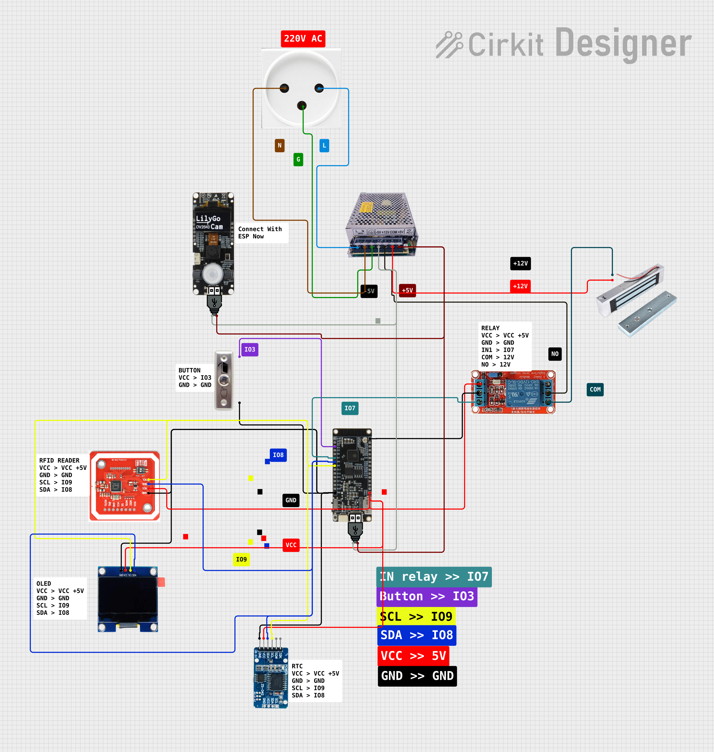
NFC-Enabled Access Control System with Real-Time Clock and OLED Display
Image of doorlock: A project utilizing REF-14S in a practical application
This circuit is designed as an access control system with time-tracking capabilities. It uses an NFC/RFID reader for authentication, a real-time clock for time-stamping events, and an OLED display for user interface, all controlled by a T8_S3 microcontroller. A relay module actuates a magnetic lock, and a button switch provides additional user input, with a switching power supply delivering the necessary voltages.
Cirkit Designer LogoOpen Project in Cirkit Designer

Explore Projects Built with REF-14S

Use Cirkit Designer to design, explore, and prototype these projects online. Some projects support real-time simulation. Click "Open Project" to start designing instantly!
Image of GPS 시스템 측정 구성도_Confirm: A project utilizing REF-14S in a practical application
Satellite-Based Timing and Navigation System with SDR and Atomic Clock Synchronization
This circuit appears to be a complex system involving power supply management, GPS and timing synchronization, and data communication. It includes a SI-TEX G1 Satellite Compass for GPS data, an XHTF1021 Atomic Rubidium Clock for precise timing, and Ettus USRP B200 units for software-defined radio communication. Power is supplied through various SMPS units and distributed via terminal blocks and DC jacks. Data communication is facilitated by Beelink MINI S12 N95 computers, RS232 splitters, and a 1000BASE-T Media Converter for network connectivity. RF Directional Couplers are used to interface antennas with the USRP units, and the entire system is likely contained within cases for protection and organization.
Cirkit Designer LogoOpen Project in Cirkit Designer
Image of doorlock: A project utilizing REF-14S in a practical application
NFC-Enabled Access Control System with Time Logging
This circuit is designed for access control with time tracking capabilities. It features an NFC/RFID reader for authentication, an RTC module (DS3231) for real-time clock functionality, and an OLED display for user interaction. A 12V relay controls a magnetic lock, which is activated upon successful NFC/RFID authentication, and a button switch is likely used for manual operation or input. The T8_S3 microcontroller serves as the central processing unit, interfacing with the NFC/RFID reader, RTC, OLED, and relay to manage the access control logic.
Cirkit Designer LogoOpen Project in Cirkit Designer
Image of Cellion-Tesla: A project utilizing REF-14S in a practical application
Modular Power Distribution System with Multiple SMPS Units and 120V Outlet
This circuit is designed to convert 240V AC power to both 12V and 24V DC outputs using multiple SMPS units. Terminal blocks are used to organize and distribute the power, while a 120V outlet provides additional AC power access. The circuit is likely used for powering various electronic devices that require different voltage levels.
Cirkit Designer LogoOpen Project in Cirkit Designer
Image of doorlock: A project utilizing REF-14S in a practical application
NFC-Enabled Access Control System with Real-Time Clock and OLED Display
This circuit is designed as an access control system with time-tracking capabilities. It uses an NFC/RFID reader for authentication, a real-time clock for time-stamping events, and an OLED display for user interface, all controlled by a T8_S3 microcontroller. A relay module actuates a magnetic lock, and a button switch provides additional user input, with a switching power supply delivering the necessary voltages.
Cirkit Designer LogoOpen Project in Cirkit Designer

Common Applications and Use Cases

  • Analog-to-Digital Converters (ADCs)
  • Digital-to-Analog Converters (DACs)
  • Precision Measurement Systems
  • Voltage Regulators
  • Calibration Equipment

Technical Specifications

Key Technical Details

Parameter Value
Output Voltage 2.5V, 5V, 10V
Input Voltage Range 4V to 30V
Output Current 10mA (max)
Temperature Coefficient 10 ppm/°C (typical)
Initial Accuracy ±0.05%
Operating Temperature Range -40°C to +85°C
Package Type TO-92, SOIC-8

Pin Configuration and Descriptions

TO-92 Package

Pin Number Pin Name Description
1 VOUT Output Voltage
2 GND Ground
3 VIN Input Voltage

SOIC-8 Package

Pin Number Pin Name Description
1 NC No Connection
2 VIN Input Voltage
3 GND Ground
4 NC No Connection
5 NC No Connection
6 VOUT Output Voltage
7 NC No Connection
8 NC No Connection

Usage Instructions

How to Use the REF-14S in a Circuit

  1. Power Supply Connection:

    • Connect the VIN pin to a stable power supply within the input voltage range (4V to 30V).
    • Connect the GND pin to the ground of the power supply.
  2. Output Voltage:

    • The VOUT pin provides the stable reference voltage. Connect this pin to the circuit where a precise voltage reference is required.
  3. Bypass Capacitor:

    • It is recommended to place a 0.1µF ceramic capacitor close to the VIN pin to filter out any noise from the power supply.

Important Considerations and Best Practices

  • Thermal Management:

    • Ensure proper thermal management, especially if the component is used in high-temperature environments. Adequate heat sinking or airflow may be necessary.
  • Noise Reduction:

    • Use low-noise power supplies and proper grounding techniques to minimize noise and ensure the stability of the reference voltage.
  • PCB Layout:

    • Place the REF-14S close to the load to minimize voltage drops and noise pickup. Use short and wide traces for the VOUT and GND connections.

Example Code for Arduino UNO

The following example demonstrates how to use the REF-14S with an Arduino UNO to provide a stable reference voltage for an ADC.

// Example code to use REF-14S with Arduino UNO
// This code reads the reference voltage and prints it to the Serial Monitor

const int refPin = A0; // Connect VOUT of REF-14S to A0

void setup() {
  Serial.begin(9600); // Initialize serial communication at 9600 baud
  analogReference(EXTERNAL); // Use external reference voltage
}

void loop() {
  int sensorValue = analogRead(refPin); // Read the analog value from A0
  float voltage = sensorValue * (5.0 / 1023.0); // Convert the analog value to voltage
  Serial.print("Reference Voltage: ");
  Serial.print(voltage);
  Serial.println(" V");
  delay(1000); // Wait for 1 second before the next reading
}

Troubleshooting and FAQs

Common Issues Users Might Face

  1. Inaccurate Output Voltage:

    • Solution: Ensure that the input voltage is within the specified range. Check for proper connections and use a low-noise power supply.
  2. Excessive Noise on Output:

    • Solution: Add a bypass capacitor (0.1µF) close to the VIN pin. Ensure proper grounding and minimize noise sources in the circuit.
  3. Overheating:

    • Solution: Implement proper thermal management techniques such as heat sinking or improved airflow.

FAQs

Q1: Can I use the REF-14S with a 3.3V power supply?

  • A1: No, the minimum input voltage for the REF-14S is 4V. Using a 3.3V power supply will not provide a stable output voltage.

Q2: What is the maximum output current of the REF-14S?

  • A2: The maximum output current is 10mA. Exceeding this limit may result in inaccurate voltage regulation or damage to the component.

Q3: Can I use the REF-14S in high-temperature environments?

  • A3: Yes, the REF-14S operates within a temperature range of -40°C to +85°C. However, ensure proper thermal management to maintain stability.

By following this documentation, users can effectively integrate the REF-14S precision voltage reference into their electronic circuits, ensuring accurate and stable voltage regulation.