How to Use TP5100: Examples, Pinouts, and Specs
Introduction
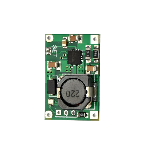
The TP5100, manufactured by Electronics Hut (Part ID: CHMOD), is a high-efficiency linear voltage regulator designed for low-dropout applications. It provides a stable and reliable output voltage with minimal power loss, making it ideal for battery-powered devices. The TP5100 is equipped with features such as thermal protection, adjustable output voltage, and high efficiency, ensuring optimal performance in a wide range of applications.
Explore Projects Built with TP5100


Explore Projects Built with TP5100
Common Applications
- Battery-powered devices (e.g., portable electronics, IoT devices)
- Power management in embedded systems
- Low-dropout voltage regulation for sensitive circuits
- Applications requiring thermal protection and high efficiency
Technical Specifications
Key Technical Details
| Parameter | Value |
|---|---|
| Input Voltage Range | 4.5V to 18V |
| Output Voltage Range | Adjustable (1.2V to 12V) |
| Maximum Output Current | 2A |
| Dropout Voltage | 0.2V (at 1A load) |
| Efficiency | Up to 90% |
| Thermal Protection | Yes |
| Operating Temperature | -40°C to +85°C |
| Package Type | SOP-8 |
Pin Configuration and Descriptions
| Pin Number | Pin Name | Description |
|---|---|---|
| 1 | VIN | Input voltage pin (4.5V to 18V) |
| 2 | GND | Ground pin |
| 3 | VOUT | Regulated output voltage pin |
| 4 | ADJ | Adjustable voltage pin (connect resistor divider) |
| 5 | EN | Enable pin (active high, logic level control) |
| 6 | NC | No connection (leave unconnected) |
| 7 | NC | No connection (leave unconnected) |
| 8 | NC | No connection (leave unconnected) |
Usage Instructions
How to Use the TP5100 in a Circuit
- Power Input: Connect the input voltage (4.5V to 18V) to the
VINpin. Ensure the input voltage is within the specified range. - Output Voltage Adjustment: Use a resistor divider network connected to the
ADJpin to set the desired output voltage. Refer to the formula in the datasheet for precise calculations. - Enable Pin: Connect the
ENpin to a logic high signal (e.g., 3.3V or 5V) to enable the regulator. Pulling this pin low disables the output. - Output Connection: Connect the load to the
VOUTpin. Ensure the load does not exceed the maximum output current of 2A. - Ground Connection: Connect the
GNDpin to the circuit ground.
Important Considerations and Best Practices
- Thermal Management: Ensure proper heat dissipation by using a heatsink or placing the component on a PCB with adequate thermal vias.
- Input Capacitor: Place a low-ESR capacitor (e.g., 10µF) close to the
VINpin to stabilize the input voltage. - Output Capacitor: Use a low-ESR capacitor (e.g., 22µF) at the
VOUTpin to ensure stable operation and reduce output noise. - Enable Pin: If the enable function is not required, connect the
ENpin toVINto keep the regulator always enabled.
Example: Connecting TP5100 to an Arduino UNO
The TP5100 can be used to power an Arduino UNO by regulating a higher input voltage (e.g., 12V) down to 5V. Below is an example circuit and Arduino code to control the EN pin.
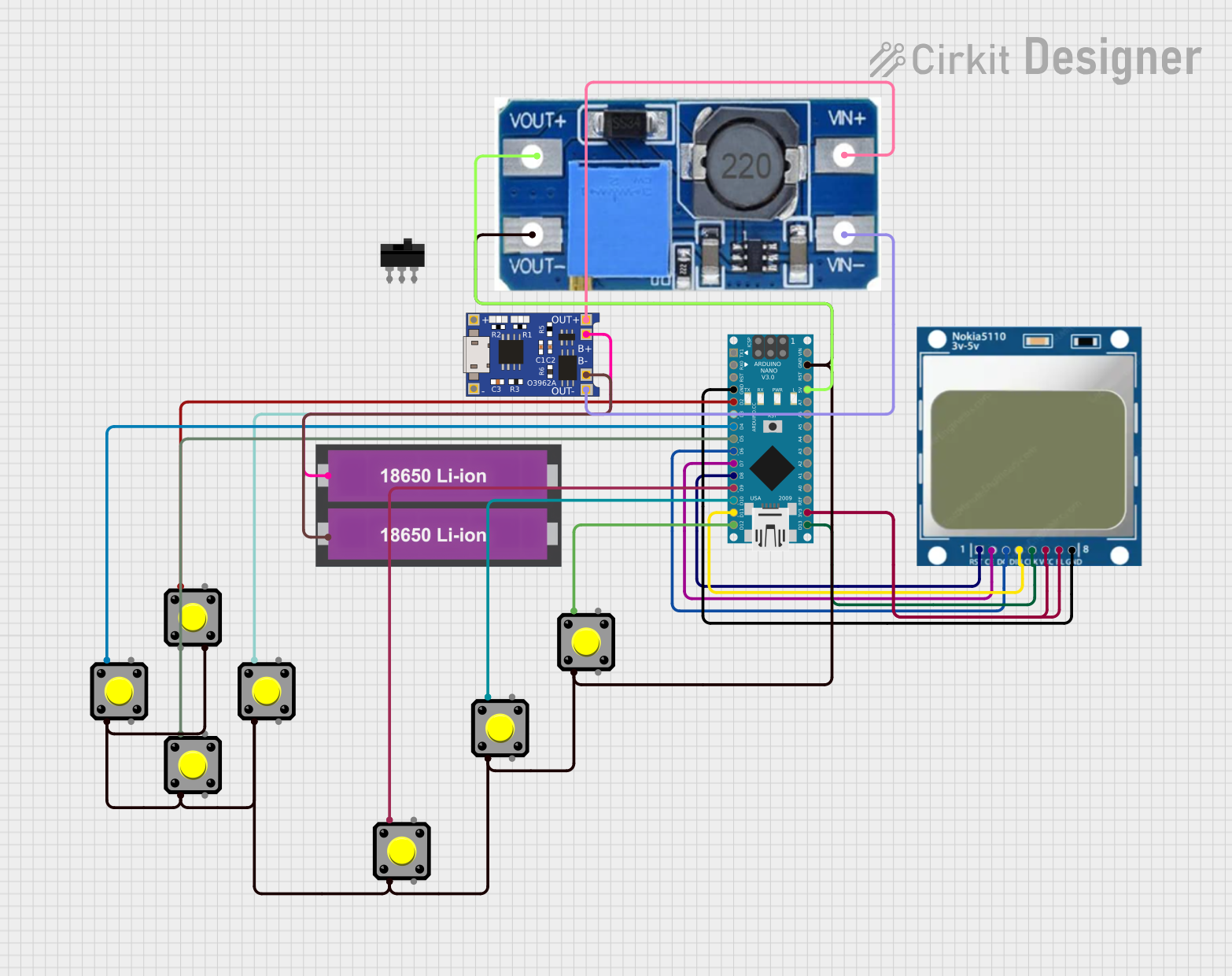
Circuit Diagram
- Connect a 12V power source to the
VINpin. - Connect the
VOUTpin to the Arduino UNO's 5V input. - Use a GPIO pin from the Arduino to control the
ENpin.
Arduino Code
// Define the pin connected to the TP5100 EN pin
const int enablePin = 7;

void setup() {
  // Set the enable pin as an output
  pinMode(enablePin, OUTPUT);

  // Enable the TP5100 by setting the pin HIGH
  digitalWrite(enablePin, HIGH);

  // Optional: Add a delay to allow the regulator to stabilize
  delay(100);
}

void loop() {
  // The TP5100 remains enabled in this example
  // Add your main code here
}
Troubleshooting and FAQs
Common Issues and Solutions
| Issue | Possible Cause | Solution |
|---|---|---|
| No output voltage | EN pin not connected or set to LOW |
Ensure the EN pin is connected to HIGH |
| Output voltage is unstable | Insufficient output capacitor | Use a low-ESR capacitor (e.g., 22µF) |
| Overheating | Excessive load or poor thermal design | Reduce load or improve heat dissipation |
| Incorrect output voltage | Resistor divider miscalculated | Verify resistor values and connections |
FAQs
Can the TP5100 handle 3.3V output?
- Yes, the TP5100 can be configured for 3.3V output using the appropriate resistor divider.
What happens if the input voltage exceeds 18V?
- The TP5100 may be damaged. Always ensure the input voltage is within the specified range.
Is the TP5100 suitable for powering microcontrollers?
- Yes, the TP5100 is ideal for powering microcontrollers due to its stable output and low dropout voltage.
Can I leave the
ADJpin unconnected?- No, the
ADJpin must be connected to a resistor divider to set the output voltage.
- No, the