Cirkit Designer Logo
Cirkit Designer
Your all-in-one circuit design IDE
Home / 
Component Documentation

How to Use Adafruit 2.13in Monochrome eInk Display: Examples, Pinouts, and Specs

Image of Adafruit 2.13in Monochrome eInk Display
Cirkit Designer LogoDesign with Adafruit 2.13in Monochrome eInk Display in Cirkit Designer

Introduction

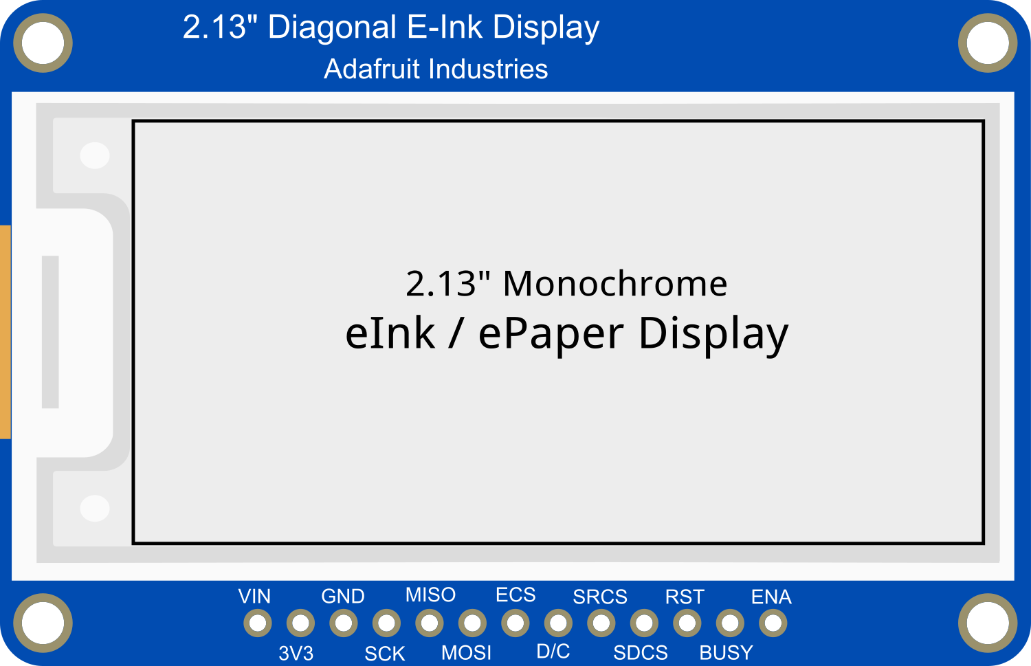
The Adafruit 2.13in Monochrome eInk Display is a compact electronic paper display module, known for its ultra-low power consumption and paper-like readability under direct sunlight. This display is perfect for applications where power efficiency is paramount, such as wearable devices, e-readers, and IoT devices that require a user interface without the power demands of a traditional LCD or OLED screen.

Explore Projects Built with Adafruit 2.13in Monochrome eInk Display

Use Cirkit Designer to design, explore, and prototype these projects online. Some projects support real-time simulation. Click "Open Project" to start designing instantly!
Arduino-Powered 2.9" Greyscale eInk Display with Checkerboard Pattern
Image of Adafruit 2.9" E-Ink Greyscale Demo: A project utilizing Adafruit 2.13in Monochrome eInk Display in a practical application
This circuit interfaces an Arduino UNO with a 2.9" Greyscale eInk display, allowing the microcontroller to control the display and render images. The Arduino is programmed to initialize the display, draw a checkerboard pattern, and invert the pattern after a delay, demonstrating the eInk display's ability to hold images without continuous updates.
Cirkit Designer LogoOpen Project in Cirkit Designer
ESP32-S3 Powered Tri-Color E-Ink Display Demo
Image of Adafruit Tri-Color E-Ink Display: A project utilizing Adafruit 2.13in Monochrome eInk Display in a practical application
This circuit integrates an ESP32-S3 microcontroller with a 2.9" Tri-Color E-Ink display, enabling the microcontroller to control the display for rendering graphics and text. The ESP32-S3 communicates with the display using SPI protocol, allowing for dynamic visual output such as animations and text updates in red, black, and white.
Cirkit Designer LogoOpen Project in Cirkit Designer
ESP8266 NodeMCU OLED Display: Wi-Fi Enabled Hello World Project
Image of oled: A project utilizing Adafruit 2.13in Monochrome eInk Display in a practical application
This circuit features an ESP8266 NodeMCU microcontroller connected to a 1.3-inch OLED display via I2C communication. The microcontroller initializes the display and renders basic graphics and text, demonstrating a simple interface for visual output.
Cirkit Designer LogoOpen Project in Cirkit Designer
Arduino 101 OLED Display Animation Project
Image of wokwi animater test: A project utilizing Adafruit 2.13in Monochrome eInk Display in a practical application
This circuit consists of an Arduino 101 microcontroller connected to a 0.96" OLED display via I2C communication. The Arduino runs a program that initializes the OLED and continuously displays an animated sequence of frames on the screen.
Cirkit Designer LogoOpen Project in Cirkit Designer

Explore Projects Built with Adafruit 2.13in Monochrome eInk Display

Use Cirkit Designer to design, explore, and prototype these projects online. Some projects support real-time simulation. Click "Open Project" to start designing instantly!
Image of Adafruit 2.9" E-Ink Greyscale Demo: A project utilizing Adafruit 2.13in Monochrome eInk Display in a practical application
Arduino-Powered 2.9" Greyscale eInk Display with Checkerboard Pattern
This circuit interfaces an Arduino UNO with a 2.9" Greyscale eInk display, allowing the microcontroller to control the display and render images. The Arduino is programmed to initialize the display, draw a checkerboard pattern, and invert the pattern after a delay, demonstrating the eInk display's ability to hold images without continuous updates.
Cirkit Designer LogoOpen Project in Cirkit Designer
Image of Adafruit Tri-Color E-Ink Display: A project utilizing Adafruit 2.13in Monochrome eInk Display in a practical application
ESP32-S3 Powered Tri-Color E-Ink Display Demo
This circuit integrates an ESP32-S3 microcontroller with a 2.9" Tri-Color E-Ink display, enabling the microcontroller to control the display for rendering graphics and text. The ESP32-S3 communicates with the display using SPI protocol, allowing for dynamic visual output such as animations and text updates in red, black, and white.
Cirkit Designer LogoOpen Project in Cirkit Designer
Image of oled: A project utilizing Adafruit 2.13in Monochrome eInk Display in a practical application
ESP8266 NodeMCU OLED Display: Wi-Fi Enabled Hello World Project
This circuit features an ESP8266 NodeMCU microcontroller connected to a 1.3-inch OLED display via I2C communication. The microcontroller initializes the display and renders basic graphics and text, demonstrating a simple interface for visual output.
Cirkit Designer LogoOpen Project in Cirkit Designer
Image of wokwi animater test: A project utilizing Adafruit 2.13in Monochrome eInk Display in a practical application
Arduino 101 OLED Display Animation Project
This circuit consists of an Arduino 101 microcontroller connected to a 0.96" OLED display via I2C communication. The Arduino runs a program that initializes the OLED and continuously displays an animated sequence of frames on the screen.
Cirkit Designer LogoOpen Project in Cirkit Designer

Common Applications and Use Cases

  • E-readers and electronic badges
  • Low-power signage
  • Wearable devices
  • IoT devices with visual output requirements
  • Battery-powered sensor displays

Technical Specifications

Key Technical Details

  • Screen Size: 2.13 inches diagonal
  • Resolution: 250x122 pixels
  • Color: Monochrome (Black and White)
  • Interface: SPI
  • Operating Voltage: 3.3V
  • Dimensions: 65.0mm x 30.2mm x 1.0mm

Pin Configuration and Descriptions

Pin Number Name Description
1 GND Ground
2 3V3 3.3V Power
3 CLK SPI Clock
4 MOSI SPI Data In
5 CS Chip Select
6 DC Data/Command Control
7 RST Reset
8 BUSY Busy State Output

Usage Instructions

How to Use the Component in a Circuit

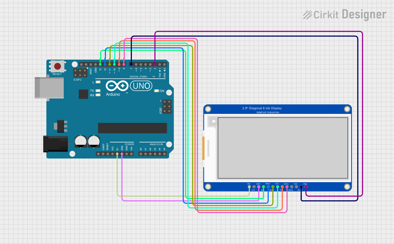
  1. Power Connections: Connect the GND pin to the ground of your power supply and the 3V3 pin to a 3.3V source.
  2. SPI Connections: Connect the CLK, MOSI, and CS pins to the corresponding SPI pins on your microcontroller.
  3. Control Pins: Connect the DC pin to a digital output on your microcontroller for data/command control, the RST pin to another digital output for resetting the display, and the BUSY pin to a digital input to read the display's busy state.

Important Considerations and Best Practices

  • Ensure that the power supply is stable and does not exceed 3.3V.
  • Use a level shifter if you are interfacing with a 5V microcontroller.
  • Avoid bending or pressing on the display to prevent damage.
  • Keep the display away from moisture and extreme temperatures.

Example Code for Arduino UNO

#include <SPI.h>
#include <Adafruit_GFX.h>
#include <Adafruit_EPD.h>

#define EPD_CS     10
#define EPD_DC     9
#define EPD_RST    8
#define EPD_BUSY   7
#define SRAM_CS    6
#define EPD_MOSI   11
#define EPD_CLK    13

// Create an instance of the display
Adafruit_SSD1675B display(122, 250, EPD_MOSI, EPD_CLK, EPD_DC, EPD_RST, EPD_CS, SRAM_CS, EPD_BUSY);

void setup() {
  display.begin(); // Initialize the display
  display.clearBuffer(); // Clear the buffer
  display.display(); // Refresh the display
  display.setTextSize(1); // Set the text size
  display.setTextColor(EPD_BLACK); // Set the text color
  display.setCursor(0,0); // Set the cursor position
  display.print("Hello, eInk!"); // Print text to the buffer
  display.display(); // Refresh the display to show the text
}

void loop() {
  // Nothing to do here
}

Ensure that the Adafruit GFX and EPD libraries are installed in your Arduino IDE before uploading this sketch. This code initializes the display, clears the buffer, and prints "Hello, eInk!" on the screen.

Troubleshooting and FAQs

Common Issues Users Might Face

  • Display not updating: Ensure all connections are secure and the correct pins are used. Also, check if the display is properly reset during setup.
  • Faint or incomplete image: Make sure the display buffer is properly cleared before writing new content and that the display is refreshed after changes.
  • Garbled output: This can be due to incorrect SPI settings or a mismatch in the communication speed. Verify the SPI connection and settings.

Solutions and Tips for Troubleshooting

  • Double-check wiring, especially the SPI and control pins.
  • Ensure that the library versions are compatible with your microcontroller.
  • Reset the display if it becomes unresponsive.
  • Consult the Adafruit forums and support channels if issues persist.

FAQs

Q: Can the display show grayscale images? A: No, this display is strictly monochrome, capable of showing black and white pixels only.

Q: How do I update only a part of the display? A: The Adafruit GFX library supports partial updates. Refer to the library documentation for functions that allow updating specific areas of the screen.

Q: Is the display sunlight-readable? A: Yes, eInk displays are known for their excellent readability in direct sunlight.

Q: How long does the image last on the display after power is removed? A: eInk displays are bistable, meaning the image can persist indefinitely without power, although it may fade over time.

For further assistance, refer to the Adafruit Learning System and the community forums for additional resources and support.