How to Use 16 Relay Modul: Examples, Pinouts, and Specs
16 Relay Module Documentation
1. Introduction
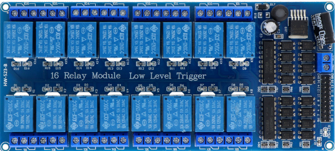
The 16 Relay Module is a versatile electronic component designed to control up to 16 individual relays on a single circuit board. Each relay acts as an electrically operated switch, allowing you to control high-voltage or high-current devices using low-power control signals. This module is widely used in automation, home control systems, industrial equipment, and IoT applications.
Common Applications:
- Home Automation: Control lights, fans, and appliances remotely.
- Industrial Automation: Manage motors, pumps, and other heavy machinery.
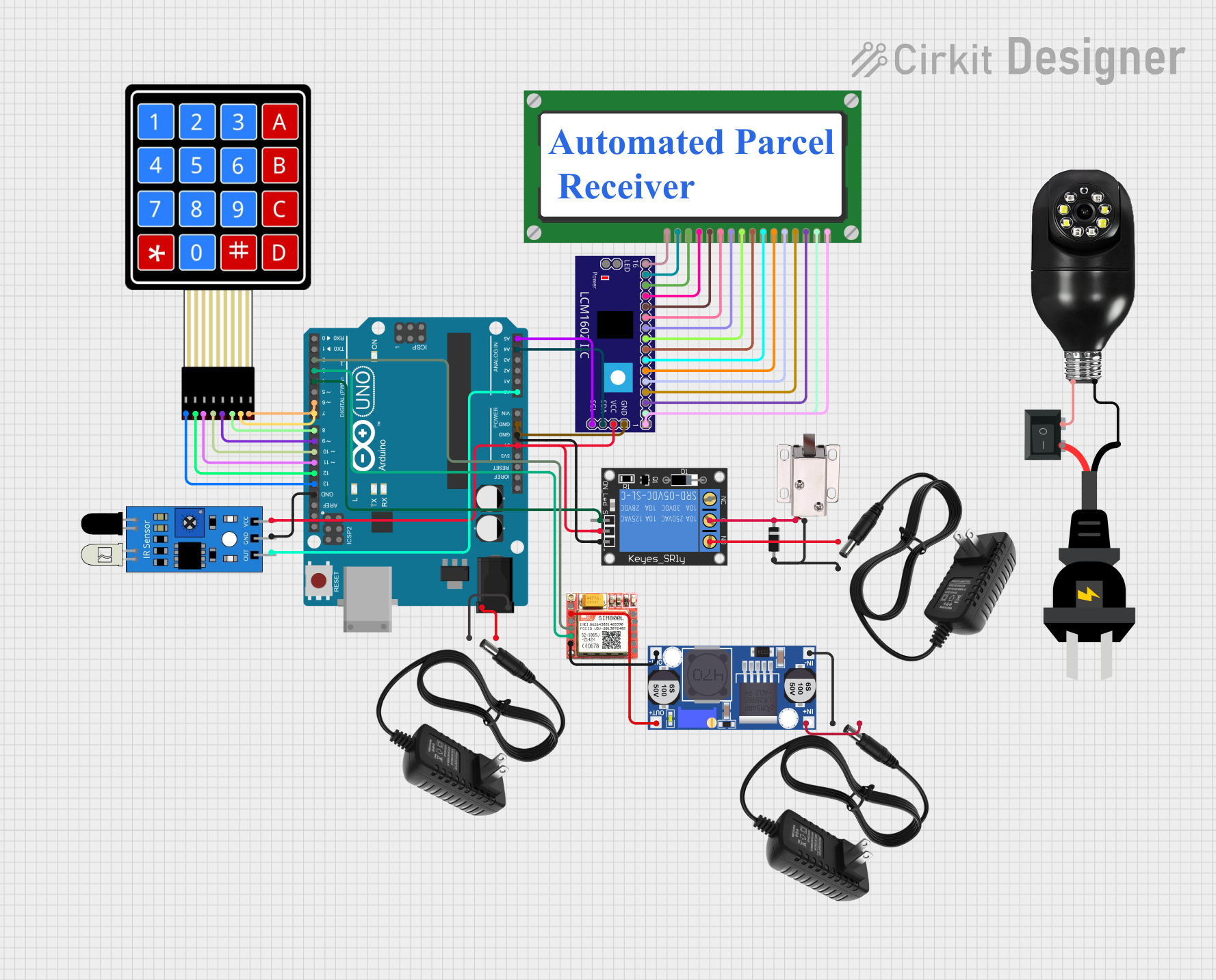
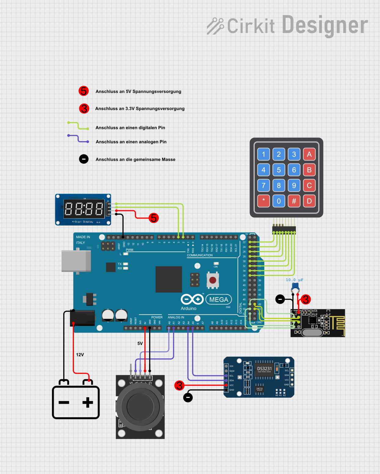
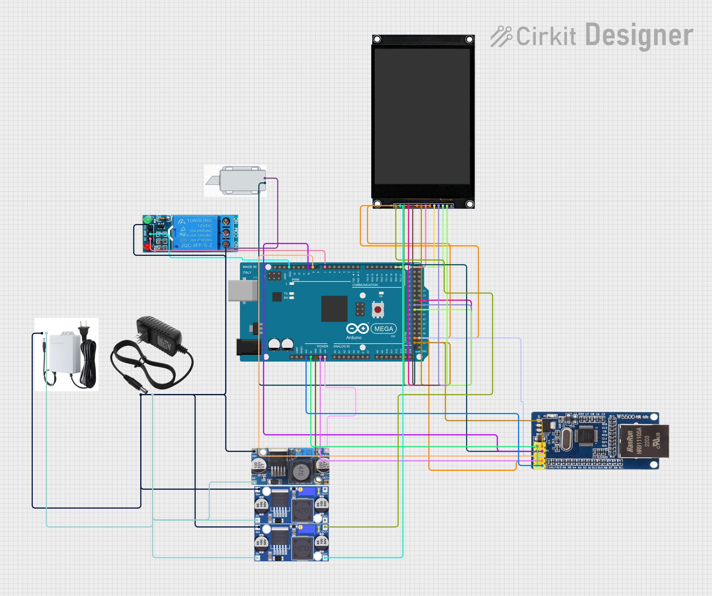
- IoT Projects: Integrate with microcontrollers like Arduino or Raspberry Pi for smart control.
- Security Systems: Operate alarms, locks, and other security devices.
- Prototyping: Test and develop circuits requiring multiple relays.
2. Technical Specifications
The following table outlines the key technical details of the 16 Relay Module:
| Parameter | Specification |
|---|---|
| Operating Voltage | 5V DC (control side) |
| Relay Voltage | 5V DC |
| Trigger Voltage | 0-5V (low-level trigger) |
| Maximum Load (AC) | 250V AC @ 10A |
| Maximum Load (DC) | 30V DC @ 10A |
| Number of Relays | 16 |
| Relay Type | SPDT (Single Pole Double Throw) |
| Isolation | Optocoupler isolation for each relay |
| Dimensions | ~190mm x 90mm x 20mm |
| Weight | ~300g |
Pin Configuration and Descriptions
The 16 Relay Module has two main sections: the control side and the load side. Below is the pin configuration:
Control Side (Input Pins):
| Pin Name | Description |
|---|---|
| VCC | 5V DC power supply for the module. |
| GND | Ground connection. |
| IN1-IN16 | Control pins for each relay. A low signal (0V) activates the corresponding relay. |
Load Side (Relay Terminals):
Each relay has three terminals:
| Terminal | Description |
|---|---|
| NO (Normally Open) | Open circuit when the relay is inactive. Closes when the relay is activated. |
| NC (Normally Closed) | Closed circuit when the relay is inactive. Opens when the relay is activated. |
| COM (Common) | Common terminal for the relay. Connects to either NO or NC depending on the relay state. |
3. Usage Instructions
Connecting the 16 Relay Module to a Microcontroller (e.g., Arduino UNO):
- Power the Module: Connect the VCC pin to the 5V pin on the Arduino and the GND pin to the Arduino's GND.
- Control Pins: Connect the IN1-IN16 pins to the desired digital output pins on the Arduino.
- Load Connections: Connect the devices you want to control to the relay terminals (NO, NC, and COM) as per your requirements.
- Code the Microcontroller: Write a program to send HIGH or LOW signals to the control pins to activate or deactivate the relays.
Important Considerations:
- Power Supply: Ensure the module is powered with a stable 5V DC supply. If the relays are switching high loads, use an external power supply for the module.
- Isolation: The module uses optocouplers for isolation, but ensure proper grounding to avoid electrical noise.
- Load Ratings: Do not exceed the maximum load ratings (250V AC @ 10A or 30V DC @ 10A) to prevent damage.
- Trigger Voltage: The module uses a low-level trigger (0V activates the relay). Ensure your microcontroller outputs are compatible.
4. Example Arduino Code
Below is an example code to control the 16 Relay Module using an Arduino UNO. This code sequentially activates each relay for 1 second and then deactivates it.
// Example code to control a 16 Relay Module with Arduino UNO
// Ensure the relay module is connected to pins 2-17 on the Arduino

// Define the control pins for the relays
const int relayPins[16] = {2, 3, 4, 5, 6, 7, 8, 9, 10, 11, 12, 13, A0, A1, A2, A3};

void setup() {
  // Initialize all relay pins as OUTPUT
  for (int i = 0; i < 16; i++) {
    pinMode(relayPins[i], OUTPUT);
    digitalWrite(relayPins[i], HIGH); // Set all relays to OFF state
  }
}

void loop() {
  // Sequentially activate each relay
  for (int i = 0; i < 16; i++) {
    digitalWrite(relayPins[i], LOW); // Activate relay (LOW signal)
    delay(1000); // Wait for 1 second
    digitalWrite(relayPins[i], HIGH); // Deactivate relay (HIGH signal)
  }
}
Code Explanation:
- Pin Initialization: The
relayPinsarray defines the Arduino pins connected to the relay module. - Setup Function: All pins are set as
OUTPUTand initialized toHIGH(relay OFF). - Loop Function: Each relay is activated (
LOW) for 1 second and then deactivated (HIGH).
5. Troubleshooting and FAQs
Common Issues and Solutions:
Relays Not Activating:
- Cause: Insufficient power supply.
- Solution: Ensure the module is powered with a stable 5V DC supply. If using an external power source, connect the GND of the module and the microcontroller.
Relays Stuck in ON/OFF State:
- Cause: Incorrect wiring or damaged relay.
- Solution: Verify the wiring and ensure the control pins are receiving the correct signals.
Electrical Noise or Interference:
- Cause: High-power loads causing interference.
- Solution: Use proper grounding and consider adding snubber circuits or flyback diodes to suppress noise.
Arduino Resets When Relays Activate:
- Cause: Power supply overload.
- Solution: Use an external power supply for the relay module and ensure the Arduino and module share a common ground.
FAQs:
Q1: Can I use the 16 Relay Module with a 3.3V microcontroller?
A1: Yes, but you may need a level shifter or transistor circuit to ensure the control signals are compatible with the module's 5V logic.
Q2: Can I control AC and DC loads simultaneously?
A2: Yes, but ensure the total load does not exceed the module's maximum ratings.
Q3: How do I know if a relay is active?
A3: Each relay has an LED indicator that lights up when the relay is activated.
This documentation provides a comprehensive guide to understanding, using, and troubleshooting the 16 Relay Module. Whether you're a beginner or an experienced user, this guide will help you integrate the module into your projects effectively.
Explore Projects Built with 16 Relay Modul

Explore Projects Built with 16 Relay Modul