How to Use Adafruit eInk Breakout Friend: Examples, Pinouts, and Specs
Introduction
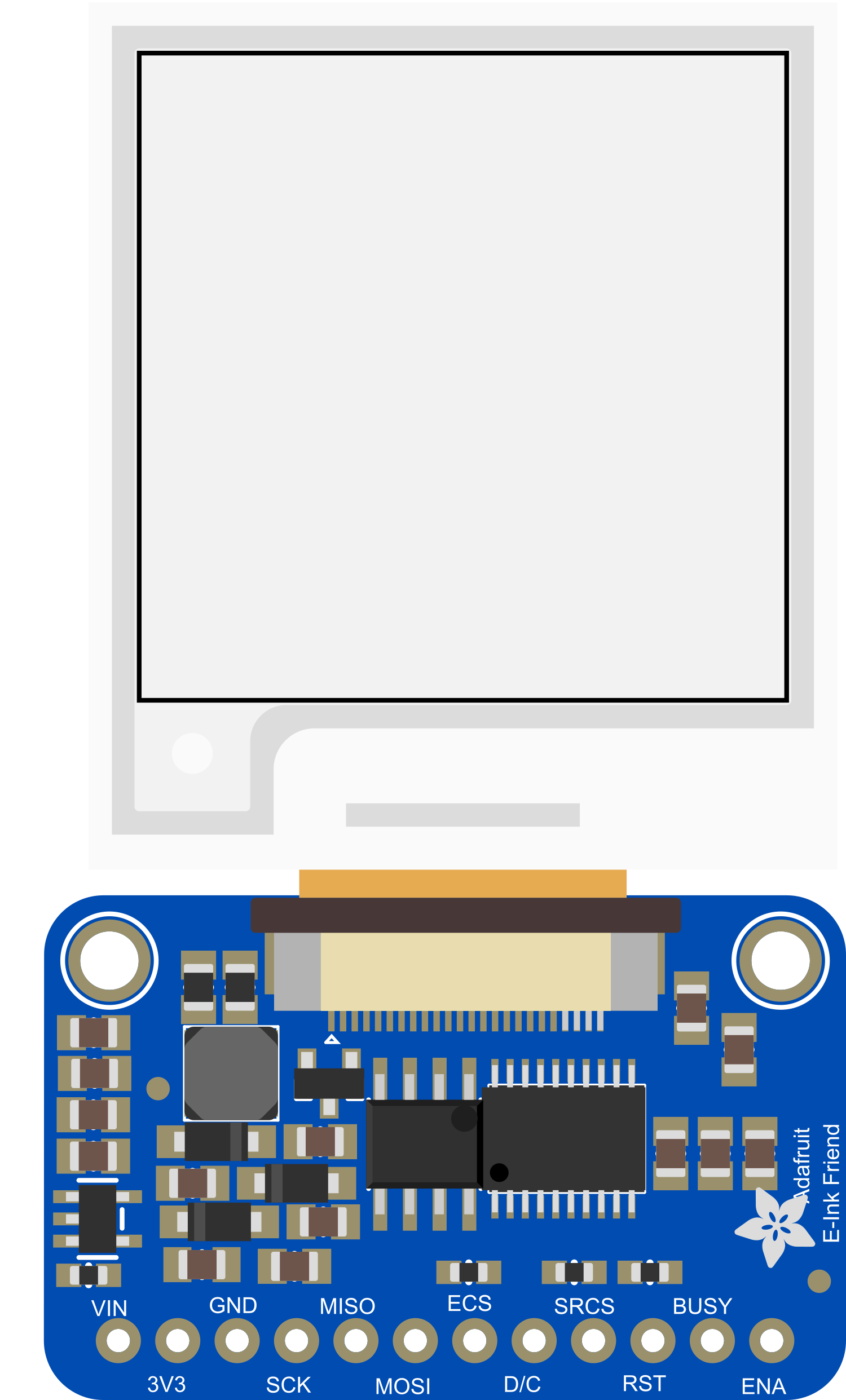
The Adafruit eInk Breakout Friend is a versatile breakout board designed to interface with e-paper displays. E-paper, or electronic paper, is a display technology that mimics the appearance of ordinary ink on paper. Unlike traditional displays, e-paper displays are highly readable under direct sunlight, consume power only when updating the image, and can hold a static image indefinitely without power. This breakout board simplifies the process of connecting an e-paper display to a microcontroller, such as an Arduino UNO, and includes onboard components to manage the display's unique electrical requirements.
Explore Projects Built with Adafruit eInk Breakout Friend
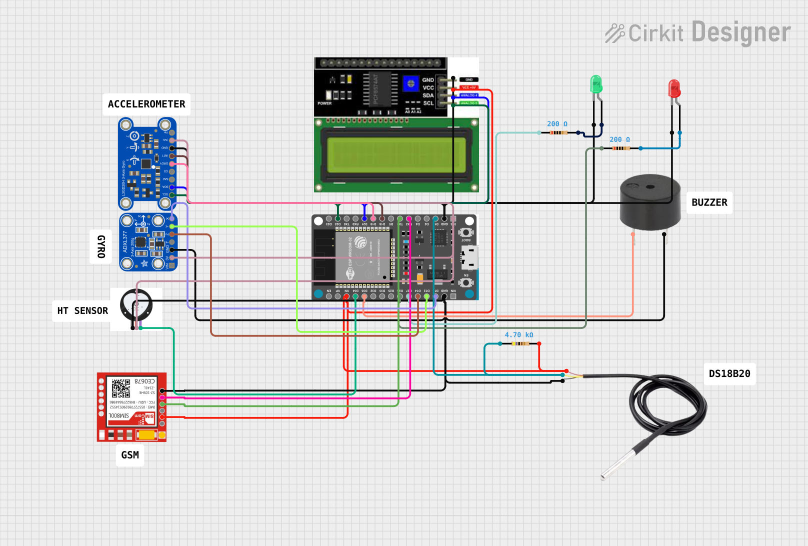
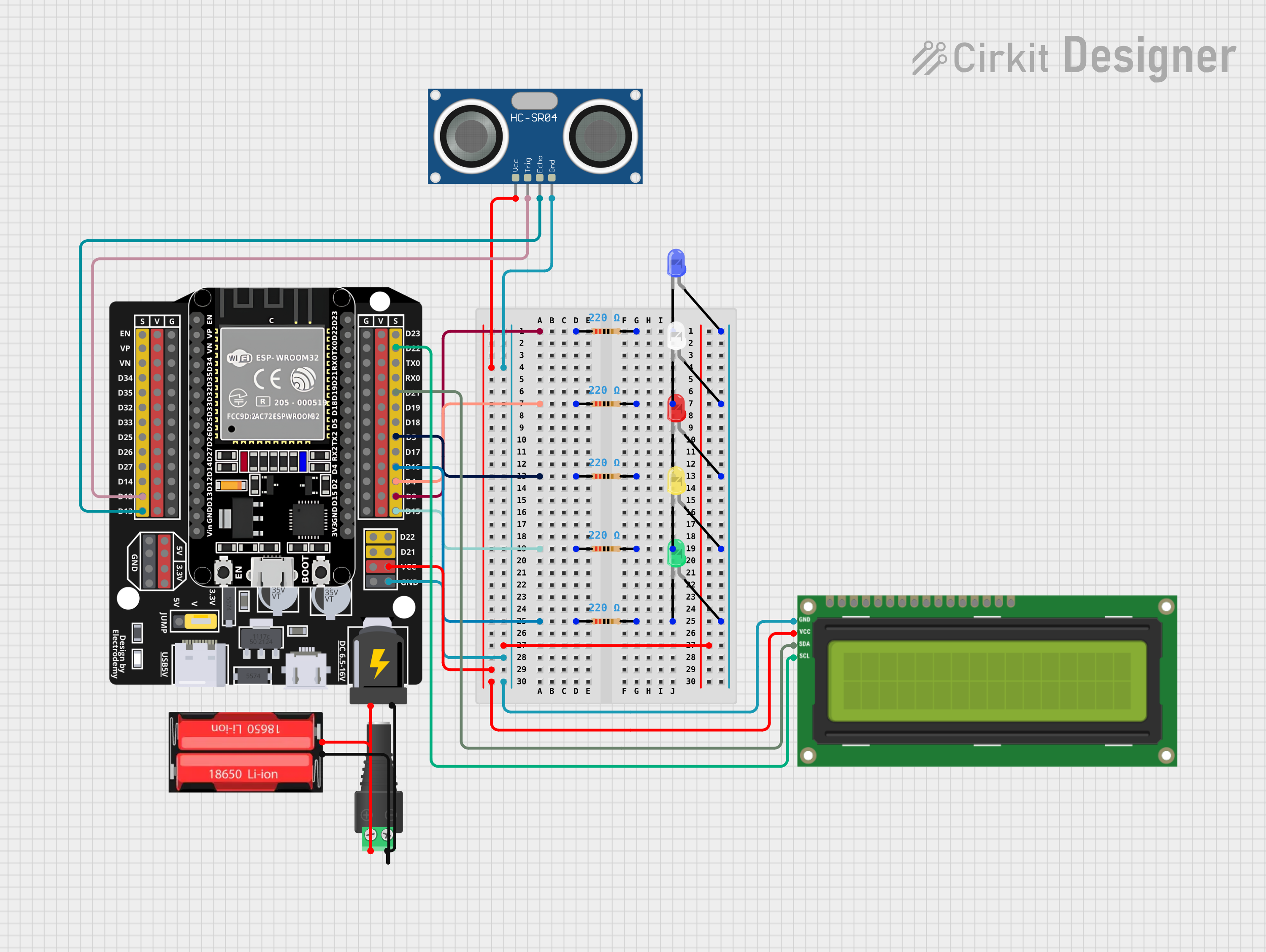

Explore Projects Built with Adafruit eInk Breakout Friend
Common Applications and Use Cases
- E-readers and electronic signage
- Low-power, battery-operated devices
- Informational displays in bright environments
- Dynamic pricing labels or information tags
- Wearable devices and smart accessories
Technical Specifications
Key Technical Details
- Operating Voltage: 3.3V to 5V
- Logic Level: 3.3V (5V tolerant)
- Supported Display Types: Various e-paper displays with a 40-pin connector
- Onboard 4-level Gray Scale
Pin Configuration and Descriptions
| Pin Number | Name | Description |
|---|---|---|
| 1 | VCC | Power supply (3.3V to 5V) |
| 2 | GND | Ground connection |
| 3 | CLK | Clock signal for SPI |
| 4 | MOSI | Master Out Slave In for SPI |
| 5 | CS | Chip Select for SPI |
| 6 | DC | Data/Command control pin |
| 7 | RST | Reset pin for the display |
| 8 | BUSY | Busy state output from the display |
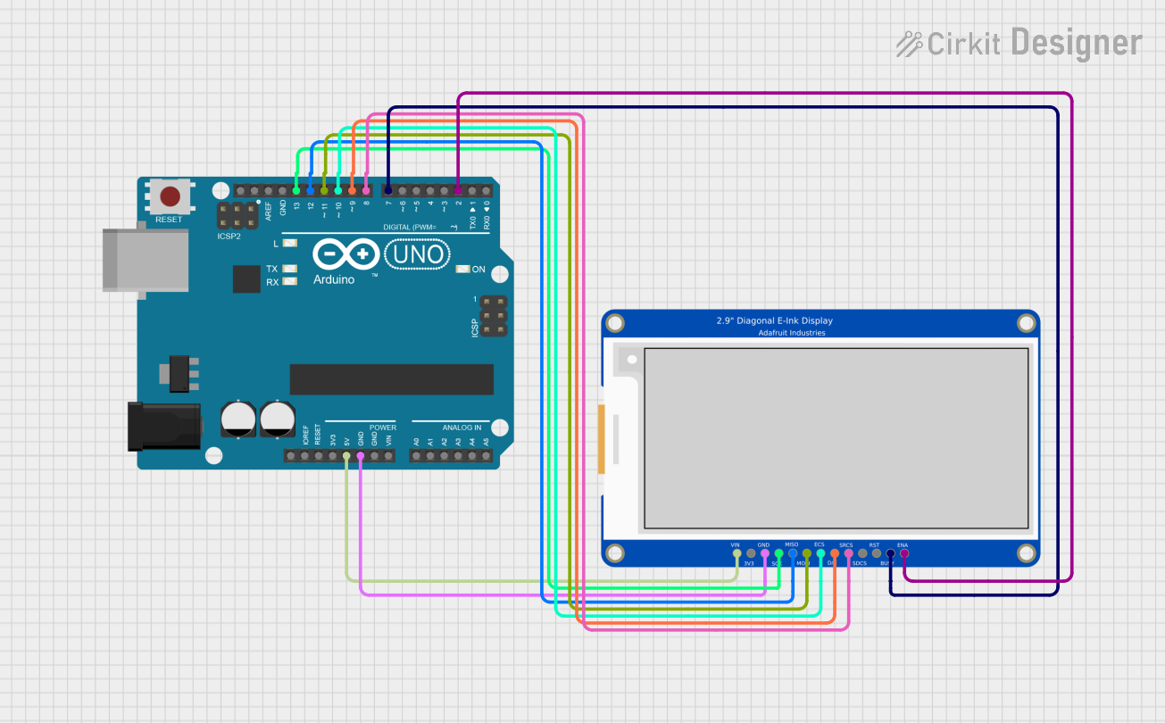
Usage Instructions
Connecting to a Circuit
- Power Connections: Connect the VCC pin to a 3.3V or 5V power supply and the GND pin to the ground.
- SPI Connections: Connect CLK, MOSI, and CS to the corresponding SPI pins on your microcontroller.
- Control Pins: Connect the DC, RST, and BUSY pins to available digital I/O pins on your microcontroller.
Important Considerations and Best Practices
- Power Supply: Ensure that the power supply is within the specified voltage range and is capable of supplying adequate current.
- Logic Levels: While the board is 5V tolerant, it is designed to operate at 3.3V logic levels. Use level shifters if necessary when interfacing with 5V logic microcontrollers.
- Display Connection: Handle the e-paper display carefully and ensure a secure connection to the 40-pin connector.
- Updating the Display: Minimize the frequency of display updates to conserve power and extend the lifespan of the e-paper display.
Example Code for Arduino UNO
#include <SPI.h>
#include <Adafruit_GFX.h>
#include <Adafruit_EPD.h>

// Pin definitions for the Adafruit eInk Breakout Friend
#define EPD_CS     10
#define EPD_DC     9
#define EPD_RST    8
#define EPD_BUSY   7
#define SRAM_CS    6
#define EPD_MOSI   11
#define EPD_CLK    13

// Create an instance of the display
Adafruit_IL0373 display(104, 212, EPD_DC, EPD_RST, EPD_CS, SRAM_CS, EPD_MOSI, EPD_CLK, EPD_BUSY);

void setup() {
  // Initialize the display
  display.begin();

  // Clear the buffer
  display.clearBuffer();

  // Draw some text on the screen
  display.setCursor(10, 10);
  display.setTextSize(1);
  display.print("Hello, eInk!");

  // Display the image
  display.display();
}

void loop() {
  // Nothing to do here
}
Code Comments
- The example code includes the necessary libraries for the eInk display.
- Pin definitions match the Adafruit eInk Breakout Friend's pinout.
- The
Adafruit_IL0373object is initialized with the display's resolution and pin configuration. - The
setup()function initializes the display, clears the buffer, and prints "Hello, eInk!" on the screen. - The
display.display()function pushes the buffer to the e-paper display. - The
loop()function is empty because the display retains the image without needing power or updates.
Troubleshooting and FAQs
Common Issues
- Display Not Updating: Ensure that all connections are secure and that the correct pins are used for SPI and control signals.
- Garbled or Incomplete Image: Check that the display buffer is correctly initialized and that the display is not being updated too frequently.
- No Image After Power Cycle: Remember that the e-paper display will retain the last image shown before power was removed. Ensure that the
display()function is called after any changes to the buffer.
Solutions and Tips for Troubleshooting
- Check Connections: Verify that all connections are correct and secure.
- Power Cycling: If the display is unresponsive, try power cycling the display by disconnecting and reconnecting the power.
- Code Review: Double-check the code for any errors in the pin definitions or display initialization.
- Library Versions: Ensure that you are using the latest version of the Adafruit EPD library.
FAQs
Q: Can I use the Adafruit eInk Breakout Friend with a 5V microcontroller? A: Yes, the breakout board is 5V tolerant, but ensure that the logic levels are compatible.
Q: How often can I update the e-paper display? A: E-paper displays are not designed for high refresh rates. Update the display only when necessary to avoid wearing out the display.
Q: Can I use the Adafruit eInk Breakout Friend with displays from other manufacturers? A: The breakout board is designed for displays with a 40-pin connector. Check the display's datasheet for compatibility with the driver chip and pinout used by the Adafruit eInk Breakout Friend.