Cirkit Designer
Your all-in-one circuit design IDE
Home /
Component Documentation
How to Use 4 Digit Seven Segment Display (Simulator): Examples, Pinouts, and Specs
Introduction
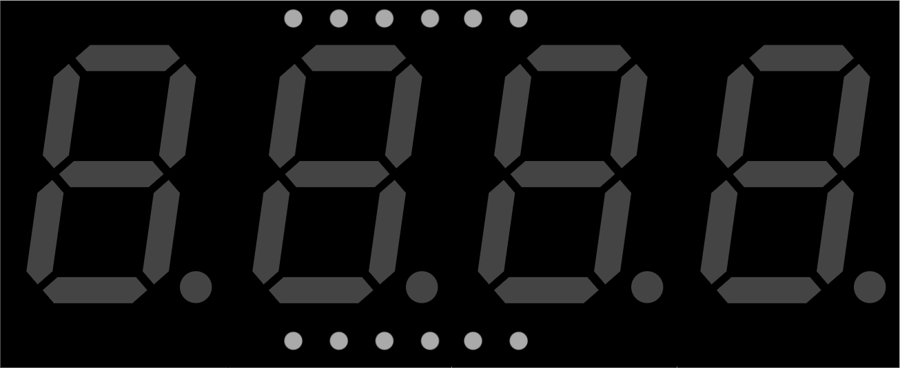
The 4 Digit Seven Segment Display is a versatile and widely used electronic component designed to display numerical information. It consists of four individual seven-segment displays, each capable of showing digits from 0 to 9. This component is commonly used in digital clocks, electronic meters, and other devices that require numerical output.
Explore Projects Built with 4 Digit Seven Segment Display (Simulator)
Arduino UNO 4-Digit 7-Segment Display Counter
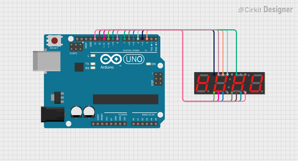
This circuit uses an Arduino UNO to control a 4-digit 7-segment display. The Arduino is programmed to sequentially display the numbers 1, 2, 3, and 4 on the display by driving the appropriate segments and digits.
Arduino UNO 4-Digit Seven Segment Display Counter
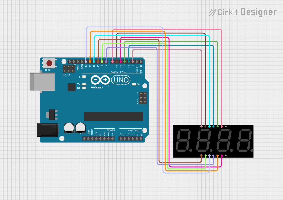
This circuit uses an Arduino UNO to control a 4-digit seven-segment display. The Arduino runs a program that counts up in deci-seconds and displays the count on the seven-segment display using the SevSeg library.
Arduino UNO Controlled Seven Segment Display
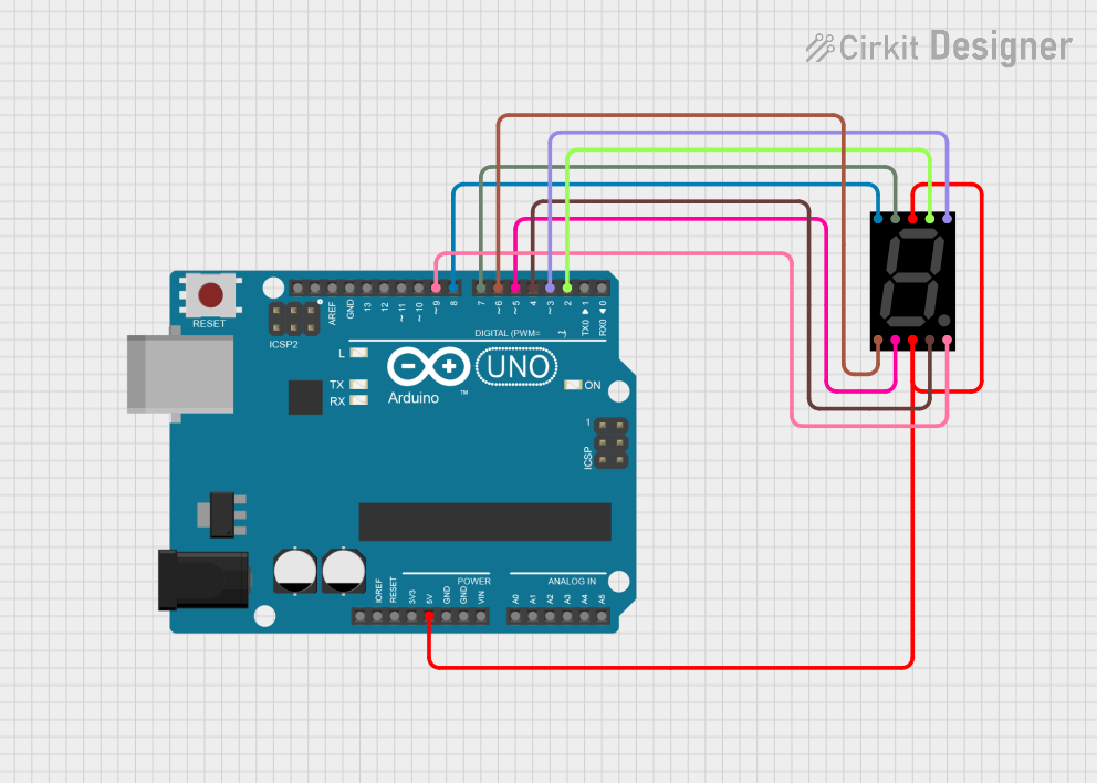
This circuit utilizes an Arduino UNO to control a seven-segment display, allowing it to display digits from 0 to 9 in a sequential manner. The Arduino is programmed to set the appropriate pins high or low to illuminate the segments of the display, creating the desired digit patterns. The display updates every second, providing a simple visual output for numerical representation.
Arduino UNO Controlled Seven Segment Display with Pushbutton Interaction
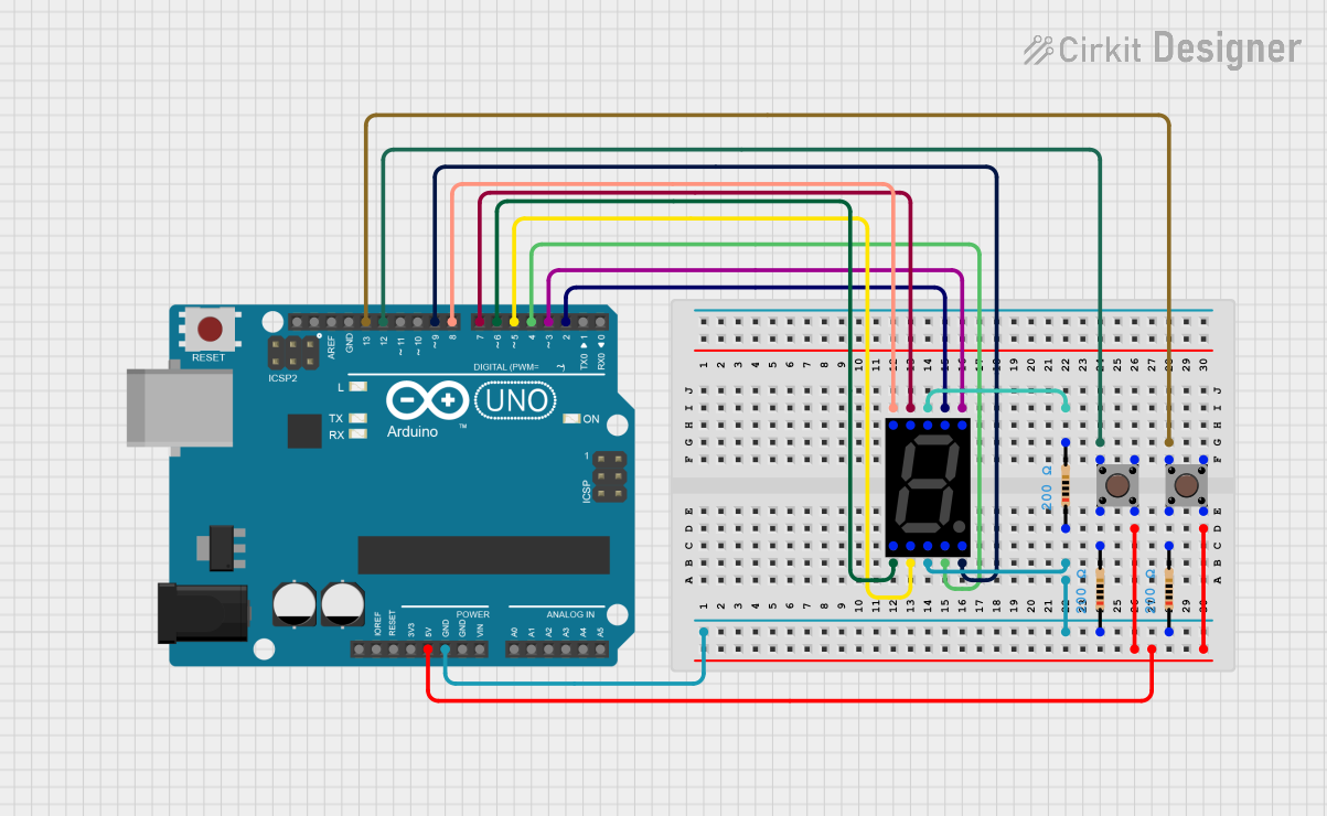
This is a user-interactive circuit where an Arduino UNO microcontroller drives a seven-segment display and reads input from two pushbuttons. The display's segments are individually controlled by the Arduino, and the pushbuttons are set up to provide user input, potentially to change the displayed digit or trigger other actions.
Explore Projects Built with 4 Digit Seven Segment Display (Simulator)
Arduino UNO 4-Digit 7-Segment Display Counter
This circuit uses an Arduino UNO to control a 4-digit 7-segment display. The Arduino is programmed to sequentially display the numbers 1, 2, 3, and 4 on the display by driving the appropriate segments and digits.
Arduino UNO 4-Digit Seven Segment Display Counter
This circuit uses an Arduino UNO to control a 4-digit seven-segment display. The Arduino runs a program that counts up in deci-seconds and displays the count on the seven-segment display using the SevSeg library.
Arduino UNO Controlled Seven Segment Display
This circuit utilizes an Arduino UNO to control a seven-segment display, allowing it to display digits from 0 to 9 in a sequential manner. The Arduino is programmed to set the appropriate pins high or low to illuminate the segments of the display, creating the desired digit patterns. The display updates every second, providing a simple visual output for numerical representation.
Arduino UNO Controlled Seven Segment Display with Pushbutton Interaction
This is a user-interactive circuit where an Arduino UNO microcontroller drives a seven-segment display and reads input from two pushbuttons. The display's segments are individually controlled by the Arduino, and the pushbuttons are set up to provide user input, potentially to change the displayed digit or trigger other actions.
Common Applications and Use Cases
- Digital clocks and timers
- Electronic meters and counters
- Scoreboards
- Temperature and humidity displays
- DIY electronics projects
Technical Specifications
Key Technical Details
| Parameter | Value |
|---|---|
| Operating Voltage | 3.3V - 5V |
| Operating Current | 20mA per segment (typical) |
| Power Consumption | Varies based on usage |
| Display Type | Common Anode or Common Cathode |
| Number of Digits | 4 |
| Segment Configuration | 7 segments + decimal point per digit |
Pin Configuration and Descriptions
Common Anode Configuration
| Pin Number | Description |
|---|---|
| 1 | Segment E |
| 2 | Segment D |
| 3 | Digit 4 (Common Anode) |
| 4 | Segment C |
| 5 | Segment DP (Decimal Point) |
| 6 | Segment B |
| 7 | Digit 3 (Common Anode) |
| 8 | Segment A |
| 9 | Digit 2 (Common Anode) |
| 10 | Segment F |
| 11 | Digit 1 (Common Anode) |
| 12 | Segment G |
Common Cathode Configuration
| Pin Number | Description |
|---|---|
| 1 | Segment E |
| 2 | Segment D |
| 3 | Digit 4 (Common Cathode) |
| 4 | Segment C |
| 5 | Segment DP (Decimal Point) |
| 6 | Segment B |
| 7 | Digit 3 (Common Cathode) |
| 8 | Segment A |
| 9 | Digit 2 (Common Cathode) |
| 10 | Segment F |
| 11 | Digit 1 (Common Cathode) |
| 12 | Segment G |
Usage Instructions
How to Use the Component in a Circuit
- Identify the Configuration: Determine whether your display is common anode or common cathode.
- Connect Power: Connect the common anode or cathode pins to the appropriate power supply (VCC for common anode, GND for common cathode).
- Connect Segments: Connect the segment pins (A-G and DP) to the corresponding output pins of your microcontroller or driver IC.
- Control Digits: Use multiplexing to control which digit is active at any given time, allowing you to display different numbers on each digit.
Important Considerations and Best Practices
- Current Limiting Resistors: Always use current limiting resistors for each segment to prevent damage to the display.
- Multiplexing: Use multiplexing techniques to control multiple digits with fewer microcontroller pins.
- Brightness Control: Adjust the brightness by varying the current through the segments or by using PWM (Pulse Width Modulation).
Example Code for Arduino UNO
// Example code to drive a 4 Digit Seven Segment Display with Arduino UNO
// This example assumes a common cathode display

const int segmentPins[] = {2, 3, 4, 5, 6, 7, 8, 9}; // A, B, C, D, E, F, G, DP
const int digitPins[] = {10, 11, 12, 13}; // Digit 1, 2, 3, 4

const byte digitPatterns[10] = {
  B00111111, // 0
  B00000110, // 1
  B01011011, // 2
  B01001111, // 3
  B01100110, // 4
  B01101101, // 5
  B01111101, // 6
  B00000111, // 7
  B01111111, // 8
  B01101111  // 9
};

void setup() {
  for (int i = 0; i < 8; i++) {
    pinMode(segmentPins[i], OUTPUT);
  }
  for (int i = 0; i < 4; i++) {
    pinMode(digitPins[i], OUTPUT);
  }
}

void loop() {
  displayNumber(1234); // Example number to display
}

void displayNumber(int number) {
  for (int digit = 0; digit < 4; digit++) {
    int digitValue = number % 10;
    number /= 10;
    displayDigit(digit, digitValue);
    delay(5); // Small delay for multiplexing
  }
}

void displayDigit(int digit, int value) {
  for (int i = 0; i < 4; i++) {
    digitalWrite(digitPins[i], HIGH); // Turn off all digits
  }
  for (int i = 0; i < 8; i++) {
    digitalWrite(segmentPins[i], bitRead(digitPatterns[value], i));
  }
  digitalWrite(digitPins[digit], LOW); // Turn on the current digit
}
Troubleshooting and FAQs
Common Issues Users Might Face
- Display Not Lighting Up: Check power connections and ensure the common anode/cathode is connected correctly.
- Incorrect Digits Displayed: Verify the segment connections and ensure the correct digit patterns are being used.
- Dim Display: Ensure current limiting resistors are of appropriate value and check power supply voltage.
Solutions and Tips for Troubleshooting
- Check Connections: Double-check all wiring and connections to ensure they match the pin configuration.
- Use a Multimeter: Measure voltages and currents to ensure they are within the specified range.
- Test Segments Individually: Test each segment individually to isolate any faulty connections or components.
By following this documentation, users should be able to effectively utilize the 4 Digit Seven Segment Display in their projects, whether they are beginners or experienced electronics enthusiasts.