How to Use CONN D-SUB PLUG 9POS SOLDER CUP: Examples, Pinouts, and Specs
Introduction
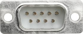
The CONN D-SUB PLUG 9POS SOLDER CUP (Manufacturer Part ID: A-DS 09 LL/Z) is a 9-position D-subminiature connector manufactured by Assmann WSW Components. This connector is designed for soldering and is widely used in electronic devices for serial communication and data transfer. Its robust design and reliable performance make it a popular choice for industrial, commercial, and consumer applications.
Explore Projects Built with CONN D-SUB PLUG 9POS SOLDER CUP


Explore Projects Built with CONN D-SUB PLUG 9POS SOLDER CUP
Common Applications and Use Cases
- Serial Communication: Commonly used in RS-232 interfaces for data transfer.
- Embedded Systems: Connecting microcontrollers to peripherals.
- Industrial Equipment: Reliable connections in control systems.
- Test and Measurement Devices: Used in diagnostic and monitoring equipment.
- Legacy Systems: Maintaining compatibility with older hardware.
Technical Specifications
Key Technical Details
| Parameter | Specification |
|---|---|
| Connector Type | D-Subminiature Plug |
| Number of Positions | 9 |
| Mounting Type | Free Hanging (In-Line) |
| Termination Style | Solder Cup |
| Shell Material | Steel, Tin-Plated |
| Contact Material | Brass |
| Contact Finish | Gold |
| Current Rating | 5A per contact |
| Voltage Rating | 300V AC/DC |
| Operating Temperature | -55°C to +105°C |
| Insulation Resistance | ≥ 5000 MΩ |
| Dielectric Withstanding Voltage | 1000V AC for 1 minute |
Pin Configuration and Descriptions
The 9-pin D-sub connector follows the standard pinout for RS-232 communication. Below is the pin configuration:
| Pin Number | Signal Name | Description |
|---|---|---|
| 1 | DCD | Data Carrier Detect |
| 2 | RXD | Receive Data |
| 3 | TXD | Transmit Data |
| 4 | DTR | Data Terminal Ready |
| 5 | GND | Signal Ground |
| 6 | DSR | Data Set Ready |
| 7 | RTS | Request to Send |
| 8 | CTS | Clear to Send |
| 9 | RI | Ring Indicator |
Usage Instructions
How to Use the Component in a Circuit
Preparation:
- Ensure you have the correct tools, such as a soldering iron, solder wire, and heat shrink tubing.
- Verify the pinout of the connector and the device it will connect to.
Soldering:
- Strip the insulation from the wires to be connected.
- Tin the exposed wire ends and the solder cups on the connector.
- Insert each wire into the corresponding solder cup based on the pinout table.
- Apply heat and solder to secure the connection.
- Use heat shrink tubing or insulation tape to protect the soldered joints.
Mounting:
- If required, attach the connector to a panel or enclosure using screws and nuts.
- Ensure the connector is securely fastened to prevent strain on the soldered connections.
Testing:
- Use a multimeter to verify continuity between the pins and the connected wires.
- Test the connector in the actual application to ensure proper functionality.
Important Considerations and Best Practices
- Avoid Overheating: Excessive heat during soldering can damage the connector or insulation.
- Check Compatibility: Ensure the connector matches the mating part (e.g., D-sub socket) in terms of pin count and gender.
- Use Strain Relief: For applications with frequent movement, use strain relief to prevent wire breakage.
- Follow Standards: Adhere to RS-232 or other relevant standards for pin assignments and signal levels.
Example: Connecting to an Arduino UNO
The D-sub connector can be used to interface an Arduino UNO with a device using RS-232 communication. Below is an example of how to connect and program the Arduino:
Circuit Diagram
- Connect the D-sub pins to a MAX232 IC for voltage level conversion.
- Interface the MAX232 IC with the Arduino UNO's TX (Pin 1) and RX (Pin 0) pins.
Arduino Code
// Example code for serial communication using Arduino UNO
// This code sends a message over the D-sub connector every second.

void setup() {
  Serial.begin(9600); // Initialize serial communication at 9600 baud
}

void loop() {
  Serial.println("Hello from Arduino!"); // Send a message
  delay(1000); // Wait for 1 second
}
Troubleshooting and FAQs
Common Issues and Solutions
No Communication Between Devices:
- Cause: Incorrect pin connections or mismatched baud rates.
- Solution: Verify the pinout and ensure the baud rate settings match on both devices.
Intermittent Connection:
- Cause: Loose solder joints or poor strain relief.
- Solution: Inspect and re-solder connections. Use strain relief to secure wires.
Overheating During Soldering:
- Cause: Prolonged application of heat to the solder cups.
- Solution: Use a temperature-controlled soldering iron and work quickly.
Signal Noise or Interference:
- Cause: Long cable runs or poor shielding.
- Solution: Use shielded cables and ensure proper grounding.
FAQs
Q1: Can this connector be used for USB communication?
A1: No, this connector is designed for RS-232 or similar serial communication protocols, not USB.
Q2: What type of cable should I use with this connector?
A2: Use a shielded multi-core cable with a diameter suitable for the solder cups.
Q3: Is this connector suitable for outdoor use?
A3: The connector is not weatherproof. For outdoor applications, use a sealed or IP-rated version.
Q4: Can I use this connector for high-speed data transfer?
A4: The D-sub connector is suitable for low to moderate data rates, typically up to 115.2 kbps for RS-232.
By following this documentation, you can effectively integrate the CONN D-SUB PLUG 9POS SOLDER CUP into your projects and ensure reliable performance.