How to Use Sistema de control: Examples, Pinouts, and Specs
Introduction
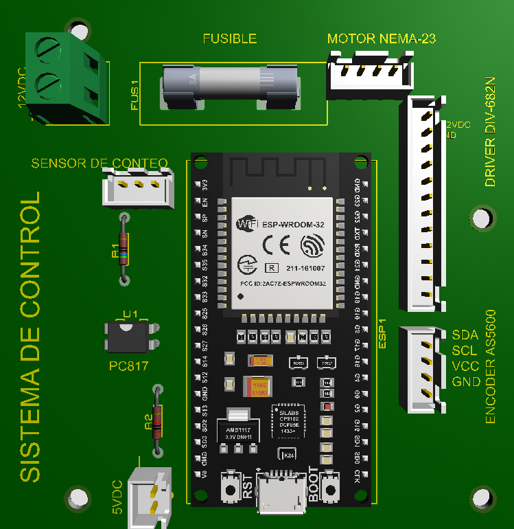
The Sistema de Control by Esp is a versatile control system designed to manage, command, and regulate the behavior of other devices or systems. It is a critical component in automation, robotics, and process control applications, ensuring efficient and effective operation of complex systems. This component is ideal for scenarios requiring precise control and monitoring, such as industrial automation, home automation, and embedded systems.
Explore Projects Built with Sistema de control
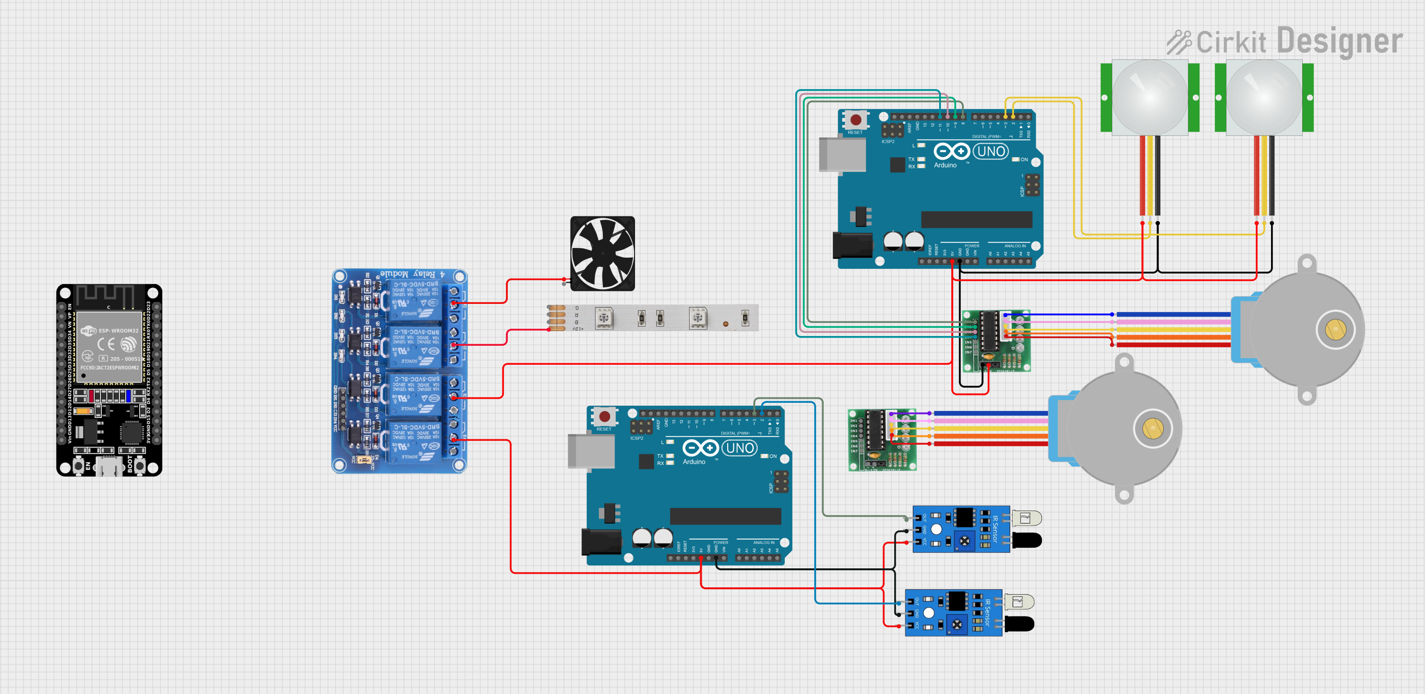

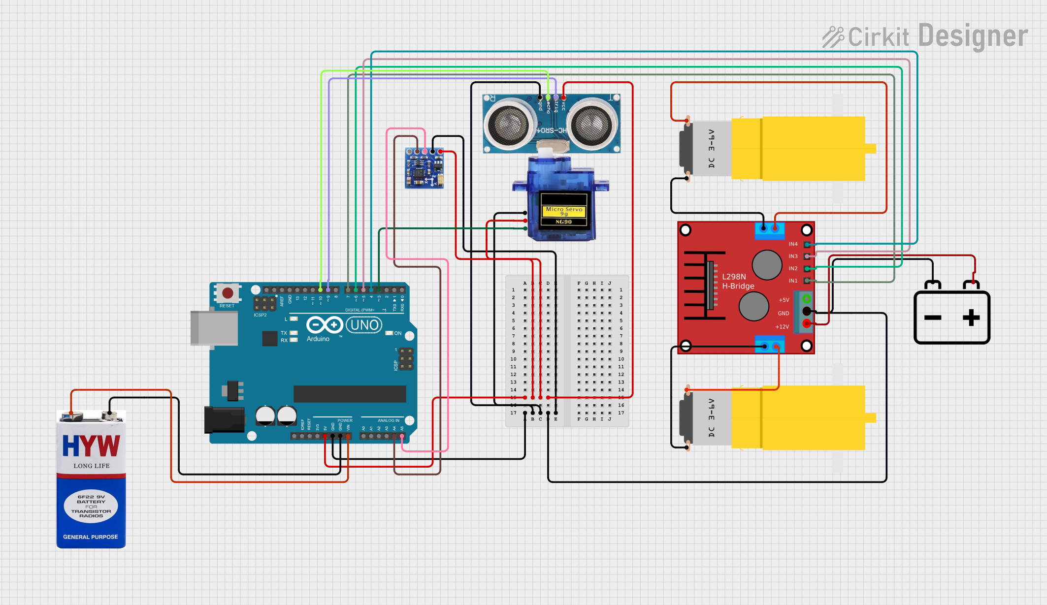
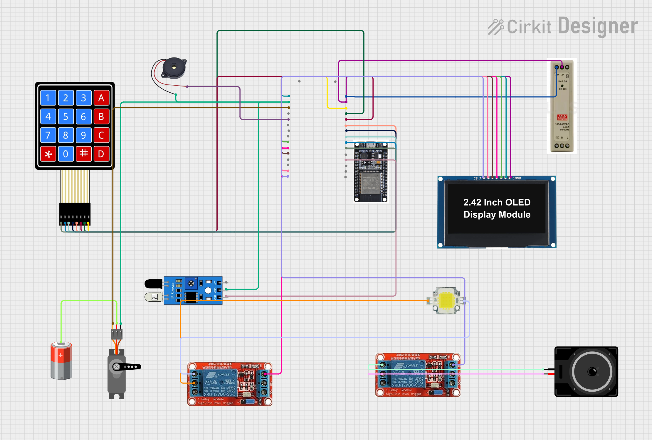
Explore Projects Built with Sistema de control
Common Applications and Use Cases
- Industrial Automation: Managing machinery and production lines.
- Robotics: Controlling robotic arms, drones, and autonomous vehicles.
- Process Control: Regulating temperature, pressure, and flow in manufacturing.
- Home Automation: Managing smart home devices like lighting, HVAC, and security systems.
- Embedded Systems: Integrating into microcontroller-based projects for real-time control.
Technical Specifications
Key Technical Details
| Parameter | Specification |
|---|---|
| Manufacturer | Esp |
| Part ID | Sistema de Control |
| Input Voltage Range | 5V to 24V DC |
| Operating Current | 50mA to 500mA (depending on load) |
| Communication Protocols | UART, I2C, SPI |
| Operating Temperature | -20°C to 85°C |
| Dimensions | 50mm x 30mm x 10mm |
| Mounting Type | PCB Mount or DIN Rail |
Pin Configuration and Descriptions
| Pin Number | Pin Name | Description |
|---|---|---|
| 1 | VCC | Power input (5V to 24V DC). Connect to the positive terminal of the power supply. |
| 2 | GND | Ground. Connect to the negative terminal of the power supply. |
| 3 | TX | UART Transmit pin. Sends data to external devices. |
| 4 | RX | UART Receive pin. Receives data from external devices. |
| 5 | SCL | I2C Clock Line. Used for communication with I2C devices. |
| 6 | SDA | I2C Data Line. Used for communication with I2C devices. |
| 7 | CS | SPI Chip Select. Activates the SPI communication. |
| 8 | MOSI | SPI Master Out Slave In. Sends data to SPI devices. |
| 9 | MISO | SPI Master In Slave Out. Receives data from SPI devices. |
| 10 | INT | Interrupt pin. Used for triggering external interrupts. |
Usage Instructions
How to Use the Component in a Circuit
- Power Connection: Connect the VCC pin to a DC power source (5V to 24V) and the GND pin to ground.
- Communication Setup: Depending on your application, connect the appropriate communication pins:
- For UART: Use the TX and RX pins.
- For I2C: Use the SCL and SDA pins.
- For SPI: Use the CS, MOSI, and MISO pins.
- Control Logic: Program your microcontroller or processor to send commands to the Sistema de Control using the selected communication protocol.
- Load Connection: Connect the devices or systems you want to control to the output terminals of the Sistema de Control.
Important Considerations and Best Practices
- Ensure the input voltage is within the specified range (5V to 24V DC) to avoid damage.
- Use appropriate pull-up resistors for I2C communication if not already integrated.
- Avoid exceeding the maximum operating current (500mA) to prevent overheating.
- Place decoupling capacitors near the power pins to reduce noise and improve stability.
- For SPI communication, ensure proper configuration of the clock polarity and phase.
Example: Connecting to an Arduino UNO
Below is an example of how to connect and use the Sistema de Control with an Arduino UNO via I2C:
Circuit Connections
- VCC: Connect to the Arduino's 5V pin.
- GND: Connect to the Arduino's GND pin.
- SCL: Connect to the Arduino's A5 pin.
- SDA: Connect to the Arduino's A4 pin.
Arduino Code Example
#include <Wire.h> // Include the Wire library for I2C communication

#define DEVICE_ADDRESS 0x40 // Replace with the actual I2C address of the Sistema de Control

void setup() {
  Wire.begin(); // Initialize I2C communication
  Serial.begin(9600); // Initialize serial communication for debugging

  // Send initialization command to the Sistema de Control
  Wire.beginTransmission(DEVICE_ADDRESS);
  Wire.write(0x01); // Example command to initialize the device
  Wire.endTransmission();

  Serial.println("Sistema de Control initialized.");
}

void loop() {
  // Example: Send a control command to the Sistema de Control
  Wire.beginTransmission(DEVICE_ADDRESS);
  Wire.write(0x02); // Example command to control the device
  Wire.endTransmission();

  delay(1000); // Wait for 1 second before sending the next command
}
Troubleshooting and FAQs
Common Issues and Solutions
Device Not Responding
- Cause: Incorrect wiring or communication protocol mismatch.
- Solution: Double-check the connections and ensure the correct protocol is used.
Overheating
- Cause: Exceeding the maximum operating current (500mA).
- Solution: Reduce the load or use an external relay for high-current devices.
Communication Errors
- Cause: Incorrect I2C address or SPI configuration.
- Solution: Verify the I2C address and ensure proper SPI clock settings.
Unstable Operation
- Cause: Power supply noise or insufficient decoupling.
- Solution: Add decoupling capacitors near the power pins.
FAQs
Q: Can the Sistema de Control operate at 3.3V?
A: No, the minimum input voltage is 5V. Use a level shifter if interfacing with 3.3V systems.Q: How do I find the I2C address of the device?
A: Use an I2C scanner sketch on your microcontroller to detect the device's address.Q: Can I use multiple communication protocols simultaneously?
A: Yes, but ensure proper configuration and avoid conflicts between protocols.Q: Is the Sistema de Control compatible with Raspberry Pi?
A: Yes, it can be used with Raspberry Pi via UART, I2C, or SPI communication.