Cirkit Designer Logo
Cirkit Designer
Your all-in-one circuit design IDE
Home / 
Component Documentation

How to Use Adafruit nRF52840 CLUE: Examples, Pinouts, and Specs

Image of Adafruit nRF52840 CLUE
Cirkit Designer LogoDesign with Adafruit nRF52840 CLUE in Cirkit Designer

Introduction

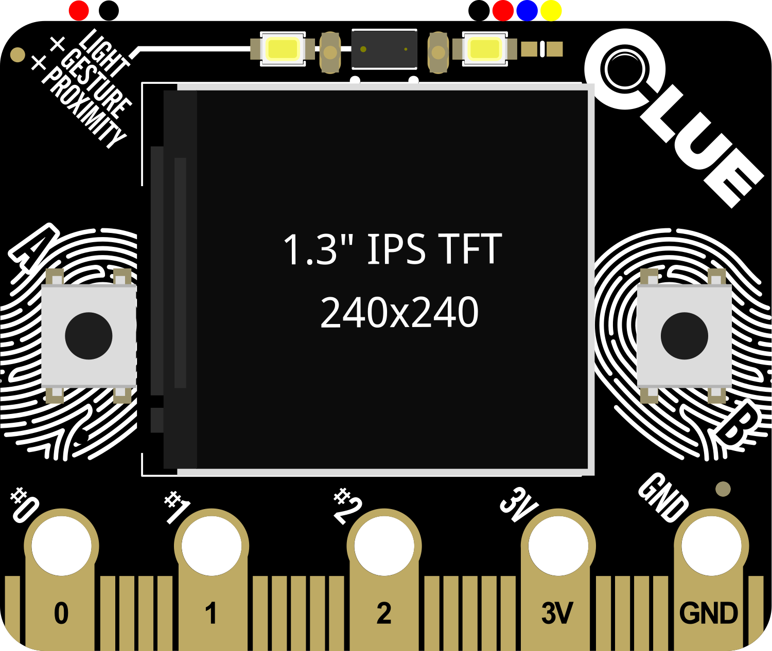
The Adafruit nRF52840 CLUE is a versatile development board that harnesses the power of the Nordic Semiconductor nRF52840 Bluetooth System on Chip (SoC). This board is designed for a wide range of applications, from IoT devices to wearable technology, thanks to its rich set of features including Bluetooth Low Energy (BLE), a plethora of sensors, and a user-friendly display. It is an ideal platform for prototyping and developing sophisticated projects that require wireless connectivity and sensor integration.

Explore Projects Built with Adafruit nRF52840 CLUE

Use Cirkit Designer to design, explore, and prototype these projects online. Some projects support real-time simulation. Click "Open Project" to start designing instantly!
Biometric and RFID Security System with Dual Adafruit Feather nRF52840 Controllers
Image of Rfid access control: A project utilizing Adafruit nRF52840 CLUE in a practical application
This circuit features two Adafruit Feather nRF52840 microcontrollers, each interfaced with an RFID-RC522 module for RFID communication and an AT24C256 external EEPROM for additional memory storage. One of the microcontrollers is also connected to an R307 Fingerprint Sensor for biometric input, and both microcontrollers are powered by a shared power supply and a coin cell breakout for backup or RTC power. The circuit is likely designed for secure access control or identification purposes, utilizing both RFID and fingerprint authentication, with data storage capabilities.
Cirkit Designer LogoOpen Project in Cirkit Designer
Arduino Nano Wireless Communication System with nRF24L01 Module
Image of drone reciever: A project utilizing Adafruit nRF52840 CLUE in a practical application
This circuit connects an nRF24L01 wireless transceiver module to an Arduino Nano microcontroller through an adapter board. The Arduino Nano is configured to communicate with the nRF24L01 via SPI (Serial Peripheral Interface), using pins D9 and D10 for chip enable (CE) and chip select (CSN), and pins D11 to D13 for the SPI bus (MOSI, MISO, SCK). An electrolytic capacitor is connected across the power supply lines likely for power stabilization.
Cirkit Designer LogoOpen Project in Cirkit Designer
Arduino Nano and NRF24L01 Based Wireless Remote Control
Image of P.T.S CAR , REMOTE , ADVANCE , FINAL V1: A project utilizing Adafruit nRF52840 CLUE in a practical application
This circuit features an Arduino Nano microcontroller interfaced with an NRF24L01 wireless transceiver module, powered by a 4 x AAA battery mount. Four pushbuttons are connected to the Arduino's digital inputs with pull-up resistors, and they are used to send different wireless commands via the NRF24L01 module when pressed. The Arduino's SPI interface (D11/MOSI, D12/MISO, D13/SCK) is used for communication with the NRF24L01, and digital pins D9 and D10 are used for the module's CE and CSN pins, respectively.
Cirkit Designer LogoOpen Project in Cirkit Designer
Battery-Powered Heart Rate Monitor using Seeed Studio nRF52840 and MAX30102
Image of Senior Design-Circuitry: A project utilizing Adafruit nRF52840 CLUE in a practical application
This circuit integrates a Seeed Studio nRF52840 microcontroller with a MAX30102 sensor module. The microcontroller powers the sensor and communicates with it via I2C protocol, enabling functionalities such as heart rate and SpO2 monitoring.
Cirkit Designer LogoOpen Project in Cirkit Designer

Explore Projects Built with Adafruit nRF52840 CLUE

Use Cirkit Designer to design, explore, and prototype these projects online. Some projects support real-time simulation. Click "Open Project" to start designing instantly!
Image of Rfid access control: A project utilizing Adafruit nRF52840 CLUE in a practical application
Biometric and RFID Security System with Dual Adafruit Feather nRF52840 Controllers
This circuit features two Adafruit Feather nRF52840 microcontrollers, each interfaced with an RFID-RC522 module for RFID communication and an AT24C256 external EEPROM for additional memory storage. One of the microcontrollers is also connected to an R307 Fingerprint Sensor for biometric input, and both microcontrollers are powered by a shared power supply and a coin cell breakout for backup or RTC power. The circuit is likely designed for secure access control or identification purposes, utilizing both RFID and fingerprint authentication, with data storage capabilities.
Cirkit Designer LogoOpen Project in Cirkit Designer
Image of drone reciever: A project utilizing Adafruit nRF52840 CLUE in a practical application
Arduino Nano Wireless Communication System with nRF24L01 Module
This circuit connects an nRF24L01 wireless transceiver module to an Arduino Nano microcontroller through an adapter board. The Arduino Nano is configured to communicate with the nRF24L01 via SPI (Serial Peripheral Interface), using pins D9 and D10 for chip enable (CE) and chip select (CSN), and pins D11 to D13 for the SPI bus (MOSI, MISO, SCK). An electrolytic capacitor is connected across the power supply lines likely for power stabilization.
Cirkit Designer LogoOpen Project in Cirkit Designer
Image of P.T.S CAR , REMOTE , ADVANCE , FINAL V1: A project utilizing Adafruit nRF52840 CLUE in a practical application
Arduino Nano and NRF24L01 Based Wireless Remote Control
This circuit features an Arduino Nano microcontroller interfaced with an NRF24L01 wireless transceiver module, powered by a 4 x AAA battery mount. Four pushbuttons are connected to the Arduino's digital inputs with pull-up resistors, and they are used to send different wireless commands via the NRF24L01 module when pressed. The Arduino's SPI interface (D11/MOSI, D12/MISO, D13/SCK) is used for communication with the NRF24L01, and digital pins D9 and D10 are used for the module's CE and CSN pins, respectively.
Cirkit Designer LogoOpen Project in Cirkit Designer
Image of Senior Design-Circuitry: A project utilizing Adafruit nRF52840 CLUE in a practical application
Battery-Powered Heart Rate Monitor using Seeed Studio nRF52840 and MAX30102
This circuit integrates a Seeed Studio nRF52840 microcontroller with a MAX30102 sensor module. The microcontroller powers the sensor and communicates with it via I2C protocol, enabling functionalities such as heart rate and SpO2 monitoring.
Cirkit Designer LogoOpen Project in Cirkit Designer

Common Applications and Use Cases

  • Wearable devices
  • Fitness trackers
  • Smart home applications
  • Educational platforms for learning electronics and programming
  • Prototyping IoT solutions
  • Environmental sensing and data logging

Technical Specifications

Key Technical Details

  • Microcontroller: Nordic nRF52840 SoC
  • Operating Voltage: 3.3V
  • Input Voltage: 5V via USB or LiPo battery
  • Onboard Sensors:
    • APDS9960 Proximity, Light, RGB, and Gesture Sensor
    • LSM6DS33 Accelerometer + Gyro
    • LIS3MDL Magnetometer
    • BMP280 Barometric Pressure & Altitude Sensor
    • SHT30 Humidity & Temperature Sensor
    • Microphone
  • Connectivity:
    • Bluetooth Low Energy (BLE 5.0)
    • NFC-A
  • Display: 1.3" 240x240 Color TFT
  • Flash Memory: 1 MB internal flash, 2 MB external QSPI flash
  • RAM: 256 KB
  • GPIO Pins: 21 available on two breakout strips
  • Analog Inputs: 6
  • PWM Outputs: All GPIOs support PWM
  • Interfaces: I2C, SPI, UART
  • USB: Native USB support

Pin Configuration and Descriptions

Pin Number Function Description
1 GND Ground
2 VOUT Regulated 3.3V output
3 AREF Analog reference voltage for ADC
4-9 A0-A5 Analog input pins
10-15 D0-D5 Digital I/O pins
16 SCK SPI clock
17 MISO SPI Master In Slave Out
18 MOSI SPI Master Out Slave In
19 RX UART receive pin
20 TX UART transmit pin
21 SDA I2C data line
22 SCL I2C clock line

Usage Instructions

How to Use the Component in a Circuit

  1. Powering the Board: Connect the board to a USB power source or attach a LiPo battery to the JST connector.
  2. Connecting Sensors/Actuators: Utilize the breakout strips to connect additional sensors or actuators to the GPIO pins.
  3. Programming the Board: Use the Arduino IDE or other compatible software to write and upload code to the board via the USB connection.

Important Considerations and Best Practices

  • Always ensure that the power supply voltage and current ratings are compatible with the nRF52840 CLUE to prevent damage.
  • When connecting external components, verify that they are within the board's logic level specifications (3.3V logic).
  • To maximize the BLE functionality, ensure that the antenna area is not obstructed by metal objects.
  • Regularly update the board's firmware and libraries to benefit from the latest features and improvements.

Troubleshooting and FAQs

Common Issues Users Might Face

  • Board Not Recognized by Computer: Check the USB cable and port. Try a different cable or port if necessary.
  • Failure to Upload Sketch: Ensure the correct board and port are selected in the Arduino IDE. Press the reset button on the board and try again.
  • Sensor Data Not Accurate: Verify that the sensors are properly initialized in your code and that there are no obstructions or sources of interference.

Solutions and Tips for Troubleshooting

  • If the board is not functioning as expected, perform a hard reset by pressing the reset button.
  • Check solder joints and wiring for any loose connections or shorts.
  • Consult the Adafruit forums and online resources for community-driven support and advice.

Example Code for Arduino UNO

#include <Wire.h>
#include <Adafruit_Sensor.h>
#include <Adafruit_BMP280.h>

Adafruit_BMP280 bmp; // I2C Interface

void setup() {
  Serial.begin(115200);
  while (!Serial); // Wait for serial port to connect
  if (!bmp.begin()) {
    Serial.println(F("Could not find a valid BMP280 sensor, check wiring!"));
    while (1);
  }
}

void loop() {
  Serial.print(F("Temperature = "));
  Serial.print(bmp.readTemperature());
  Serial.println(" *C");

  Serial.print(F("Pressure = "));
  Serial.print(bmp.readPressure());
  Serial.println(" Pa");

  Serial.print(F("Approx altitude = "));
  Serial.print(bmp.readAltitude(1013.25)); // this should be adjusted to your local forcase
  Serial.println(" m");

  delay(2000);
}

Note: The above example demonstrates how to interface the BMP280 sensor on the Adafruit nRF52840 CLUE with an Arduino UNO. Ensure that you have installed the necessary libraries and that the I2C address matches that of your sensor.

For more detailed information, visit the Adafruit Learning System and the nRF52840 CLUE product page.