
How to Use Radar HLK-LD 2413: Examples, Pinouts, and Specs
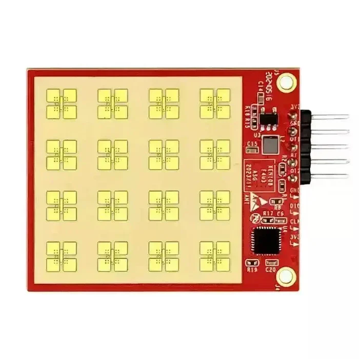
 Design with Radar HLK-LD 2413 in Cirkit Designer
Introduction
The Radar HLK-LD 2413 is a compact radar sensor designed for distance measurement and object detection. Operating in the 24 GHz frequency range, this sensor offers high accuracy and reliability, making it suitable for a wide range of applications. Its small form factor and robust design allow it to perform effectively in challenging environments.
Explore Projects Built with Radar HLK-LD 2413
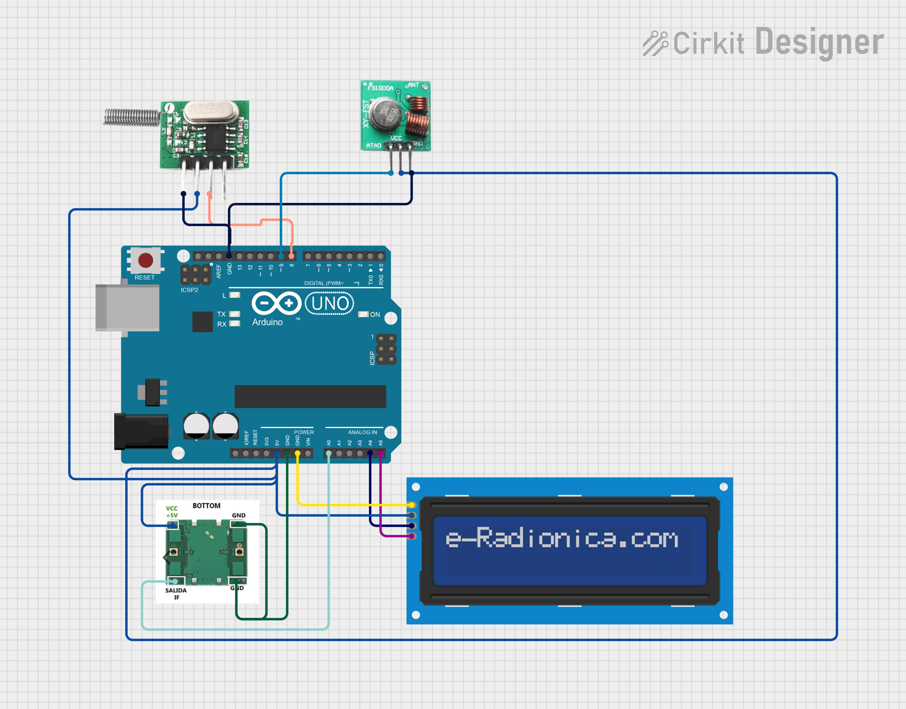 Open Project in Cirkit Designer
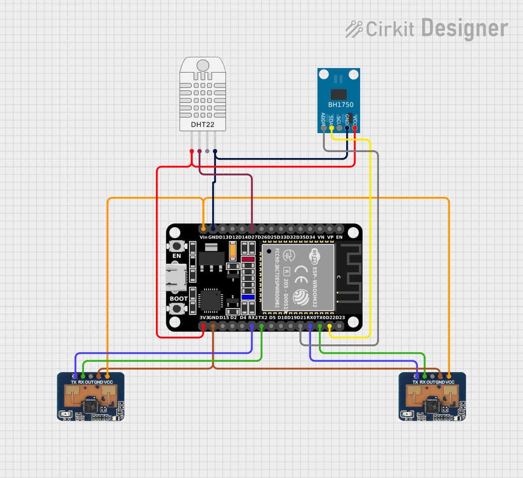 Open Project in Cirkit Designer
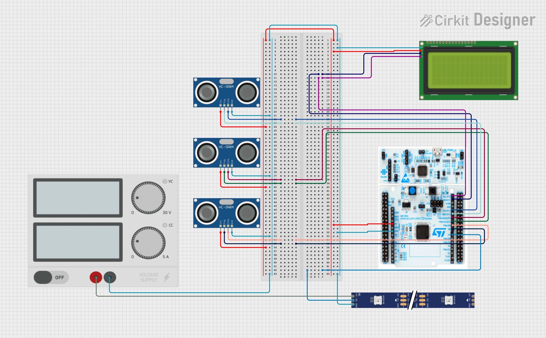 Open Project in Cirkit Designer
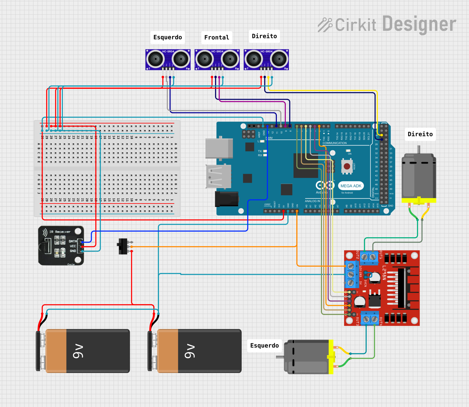 Open Project in Cirkit Designer
Explore Projects Built with Radar HLK-LD 2413
Open Project in Cirkit DesignerOpen Project in Cirkit DesignerOpen Project in Cirkit DesignerOpen Project in Cirkit DesignerCommon Applications and Use Cases
- Automotive systems (e.g., collision avoidance, parking assistance)
- Industrial automation (e.g., object detection on conveyor belts)
- Smart home devices (e.g., motion detection for security systems)
- Robotics (e.g., obstacle detection and navigation)
- Traffic monitoring and management systems
Technical Specifications
Below are the key technical details of the Radar HLK-LD 2413:
| Parameter | Value |
|---|---|
| Operating Frequency | 24 GHz |
| Detection Range | 0.3 m to 30 m |
| Operating Voltage | 5 V DC |
| Operating Current | ≤ 60 mA |
| Output Interface | UART (TTL level) |
| Communication Baud Rate | 115200 bps |
| Detection Angle | ±15° |
| Operating Temperature | -40°C to +85°C |
| Dimensions | 25 mm x 25 mm x 6 mm |
Pin Configuration and Descriptions
The Radar HLK-LD 2413 has a 4-pin interface for power and communication. The pinout is as follows:
| Pin Number | Pin Name | Description |
|---|---|---|
| 1 | VCC | Power supply input (5 V DC) |
| 2 | GND | Ground |
| 3 | TX | UART Transmit (data output from the radar module) |
| 4 | RX | UART Receive (data input to the radar module) |
Usage Instructions
How to Use the Radar HLK-LD 2413 in a Circuit
- Power Supply: Connect the
VCCpin to a stable 5 V DC power source and theGNDpin to the ground of your circuit. - UART Communication: Connect the
TXpin of the radar module to the RX pin of your microcontroller (e.g., Arduino UNO) and theRXpin of the radar module to the TX pin of the microcontroller. - Data Processing: Use the UART interface to receive distance and object detection data from the radar module. The data is transmitted in a predefined format at a baud rate of 115200 bps.
Important Considerations and Best Practices
- Ensure that the radar module is mounted securely and oriented correctly for optimal detection performance.
- Avoid placing the module near strong electromagnetic interference (EMI) sources, as this may affect its accuracy.
- Use a level shifter if your microcontroller operates at 3.3 V logic levels, as the radar module uses 5 V TTL logic.
- Maintain a clear line of sight between the radar module and the target object for accurate measurements.
Example Code for Arduino UNO
Below is an example Arduino sketch to interface with the Radar HLK-LD 2413 and read data via UART:
// Example code to interface with Radar HLK-LD 2413 using Arduino UNO
// This code reads data from the radar module and prints it to the Serial Monitor.

#include <SoftwareSerial.h>

// Define the RX and TX pins for SoftwareSerial
SoftwareSerial radarSerial(2, 3); // RX = Pin 2, TX = Pin 3

void setup() {
  // Initialize hardware serial for debugging
  Serial.begin(9600);
  Serial.println("Radar HLK-LD 2413 Test");

  // Initialize software serial for radar communication
  radarSerial.begin(115200); // Baud rate for radar module
}

void loop() {
  // Check if data is available from the radar module
  if (radarSerial.available()) {
    // Read and print the data from the radar module
    String radarData = radarSerial.readStringUntil('\n');
    Serial.println("Radar Data: " + radarData);
  }

  delay(100); // Small delay to avoid flooding the Serial Monitor
}
Troubleshooting and FAQs
Common Issues and Solutions
No Data Received from the Radar Module
- Cause: Incorrect wiring or baud rate mismatch.
- Solution: Double-check the connections between the radar module and the microcontroller. Ensure the baud rate is set to 115200 bps in your code.
Inaccurate Distance Measurements
- Cause: Obstructions or interference in the radar's line of sight.
- Solution: Ensure there are no obstacles or reflective surfaces near the radar module that could cause signal distortion.
Module Overheating
- Cause: Operating the module outside its specified voltage range.
- Solution: Verify that the power supply provides a stable 5 V DC and does not exceed the module's current rating.
Intermittent Communication
- Cause: Loose connections or noisy power supply.
- Solution: Secure all connections and use a decoupling capacitor (e.g., 10 µF) across the power supply pins to filter noise.
FAQs
Q1: Can the Radar HLK-LD 2413 detect multiple objects simultaneously?
A1: No, the module is designed to detect the nearest object within its detection range.
Q2: Is the module waterproof?
A2: No, the Radar HLK-LD 2413 is not waterproof. It should be used in environments where it is protected from moisture.
Q3: Can I use the module with a 3.3 V microcontroller?
A3: Yes, but you will need a level shifter to safely interface the 5 V logic of the radar module with the 3.3 V logic of your microcontroller.
Q4: What is the maximum detection range of the module?
A4: The Radar HLK-LD 2413 can detect objects up to 30 meters away under optimal conditions.