How to Use BS170: Examples, Pinouts, and Specs
Introduction
The BS170 is an N-channel MOSFET (Metal-Oxide-Semiconductor Field-Effect Transistor) designed for low-power switching applications. It is widely used in electronic circuits due to its low on-resistance, fast switching speeds, and ease of use. The BS170 is particularly suitable for applications such as driving small loads, signal amplification, and interfacing with microcontrollers.
Explore Projects Built with BS170


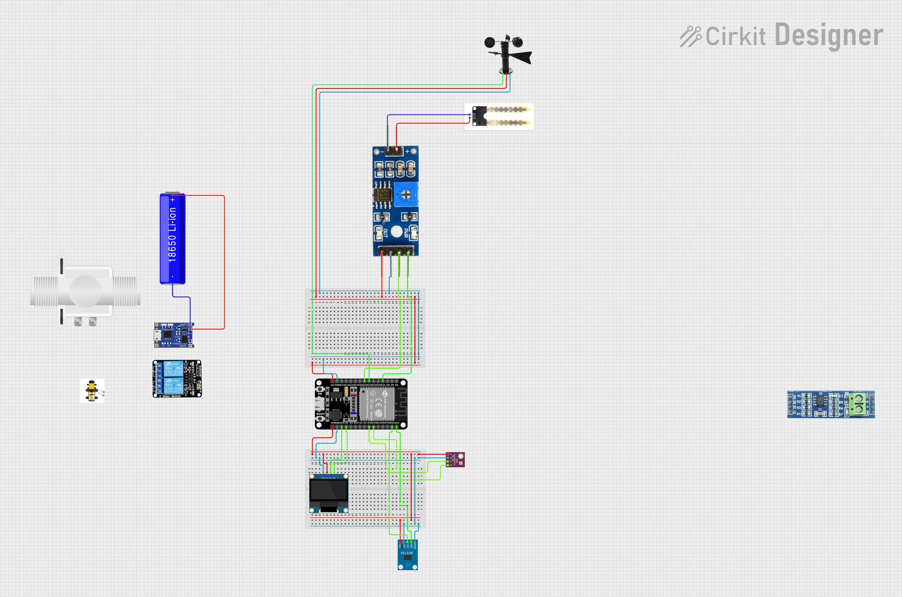
Explore Projects Built with BS170
Common Applications and Use Cases
- Low-power switching circuits
- Driving LEDs, relays, or small motors
- Signal amplification in audio or RF circuits
- Interfacing with microcontrollers like Arduino or Raspberry Pi
- General-purpose low-voltage switching
Technical Specifications
Below are the key technical details of the BS170 MOSFET:
| Parameter | Value |
|---|---|
| Type | N-Channel MOSFET |
| Maximum Drain-Source Voltage (VDS) | 60V |
| Maximum Gate-Source Voltage (VGS) | ±20V |
| Continuous Drain Current (ID) | 500mA |
| Power Dissipation (PD) | 830mW |
| On-Resistance (RDS(on)) | 5Ω (typical) at VGS = 10V |
| Gate Threshold Voltage (VGS(th)) | 2.0V - 4.0V |
| Switching Speed | Fast |
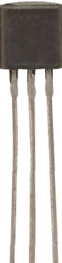
| Package Type | TO-92 |
Pin Configuration and Descriptions
The BS170 is available in a TO-92 package with three pins. The pinout is as follows:
| Pin Number | Pin Name | Description |
|---|---|---|
| 1 | Gate | Controls the MOSFET switching (input) |
| 2 | Drain | Current flows from drain to source |
| 3 | Source | Connected to ground or load return path |
Usage Instructions
How to Use the BS170 in a Circuit
- Connect the Source Pin: The source pin is typically connected to the ground or the negative terminal of the power supply.
- Connect the Drain Pin: The drain pin is connected to the load (e.g., an LED, motor, or relay).
- Control the Gate Pin: Apply a voltage to the gate pin to turn the MOSFET on or off. A voltage of 5V or higher (relative to the source) is typically sufficient to fully turn on the BS170.
Example Circuit: Driving an LED
Below is an example of how to use the BS170 to control an LED with a microcontroller like an Arduino UNO:
// Example: Controlling an LED with the BS170 MOSFET and Arduino UNO

const int gatePin = 9;  // Pin connected to the Gate of the BS170
const int ledState = HIGH;  // Set HIGH to turn on the LED, LOW to turn it off

void setup() {
  pinMode(gatePin, OUTPUT);  // Set the gate pin as an output
}

void loop() {
  digitalWrite(gatePin, ledState);  // Turn the LED on or off
  delay(1000);  // Wait for 1 second
  digitalWrite(gatePin, !ledState);  // Toggle the LED state
  delay(1000);  // Wait for 1 second
}
Important Considerations and Best Practices
- Gate Voltage: Ensure the gate voltage is within the specified range (±20V). For logic-level operation, a gate voltage of 5V is sufficient.
- Current Limiting: Use a resistor (e.g., 220Ω) in series with the gate to limit the inrush current when switching.
- Heat Dissipation: If the MOSFET is used near its maximum current rating, consider adding a heatsink to manage heat dissipation.
- Load Protection: For inductive loads (e.g., motors or relays), use a flyback diode across the load to protect the MOSFET from voltage spikes.
Troubleshooting and FAQs
Common Issues and Solutions
MOSFET Not Turning On
- Cause: Insufficient gate voltage.
- Solution: Ensure the gate voltage is at least 5V for full switching. Check the microcontroller output voltage.
Excessive Heat
- Cause: Operating near the maximum current rating or insufficient heat dissipation.
- Solution: Reduce the load current or add a heatsink to the MOSFET.
Load Not Responding
- Cause: Incorrect wiring or damaged MOSFET.
- Solution: Double-check the circuit connections. Test the MOSFET with a multimeter to ensure it is functional.
Voltage Spikes Damaging the MOSFET
- Cause: Inductive loads generating back EMF.
- Solution: Add a flyback diode across the load to suppress voltage spikes.
FAQs
Q: Can the BS170 be used with a 3.3V microcontroller?
A: The BS170 may not fully turn on with a 3.3V gate voltage. For 3.3V logic, consider using a logic-level MOSFET like the IRLZ44N.
Q: What is the maximum load the BS170 can drive?
A: The BS170 can handle a maximum continuous current of 500mA. Ensure the load does not exceed this limit.
Q: Do I need a resistor on the gate pin?
A: While not strictly necessary, a resistor (e.g., 220Ω) is recommended to limit the inrush current and protect the microcontroller.
Q: Can the BS170 be used for high-frequency switching?
A: Yes, the BS170 has fast switching speeds and is suitable for high-frequency applications, provided the load and circuit design are appropriate.
This concludes the documentation for the BS170 MOSFET.