
How to Use Transmitter TEMP: Examples, Pinouts, and Specs
 Design with Transmitter TEMP in Cirkit Designer
Introduction
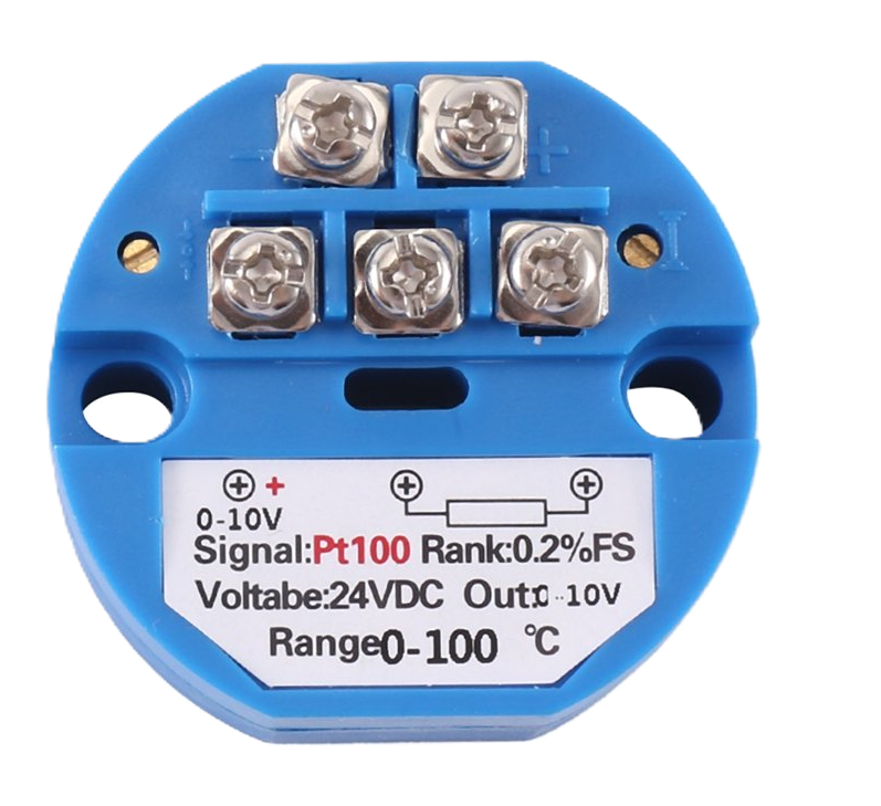
The Transmitter TEMP is a wireless device designed to send temperature data to a receiver. It is commonly used in remote monitoring applications, such as environmental monitoring, industrial automation, and smart home systems. By transmitting temperature readings wirelessly, it eliminates the need for physical connections, making it ideal for use in hard-to-reach or hazardous locations.
Explore Projects Built with Transmitter TEMP
 Open Project in Cirkit Designer
 Open Project in Cirkit Designer
 Open Project in Cirkit Designer
 Open Project in Cirkit Designer
Explore Projects Built with Transmitter TEMP
Open Project in Cirkit DesignerOpen Project in Cirkit DesignerOpen Project in Cirkit DesignerOpen Project in Cirkit DesignerTechnical Specifications
- Operating Voltage: 3.3V to 5V DC
- Operating Current: 15mA (typical)
- Transmission Frequency: 433 MHz / 2.4 GHz (depending on model)
- Transmission Range: Up to 100 meters (line of sight)
- Temperature Range: -40°C to +85°C
- Data Protocol: Serial UART (9600 baud rate by default)
- Dimensions: 30mm x 20mm x 5mm
Pin Configuration and Descriptions
| Pin | Name | Description |
|---|---|---|
| 1 | VCC | Power supply input (3.3V to 5V DC). |
| 2 | GND | Ground connection. |
| 3 | DATA | Serial data output pin for transmitting temperature data. |
| 4 | CONFIG | Configuration pin for setting transmission parameters (optional, pull to GND). |
Usage Instructions
How to Use the Transmitter TEMP in a Circuit
- Power the Device: Connect the VCC pin to a 3.3V or 5V DC power source and the GND pin to ground.
- Connect the Data Pin: Attach the DATA pin to the microcontroller's UART RX pin to receive temperature data.
- Optional Configuration: If needed, use the CONFIG pin to adjust transmission parameters (refer to the manufacturer's datasheet for details).
- Pair with a Receiver: Ensure the receiver module is set to the same frequency and protocol to successfully receive data.
Important Considerations and Best Practices
- Power Supply: Use a stable power source to avoid transmission errors.
- Antenna Placement: For optimal range, ensure the antenna is unobstructed and positioned vertically.
- Interference: Avoid placing the module near devices that operate on the same frequency to minimize interference.
- Baud Rate Matching: Ensure the microcontroller's UART baud rate matches the module's default (9600 baud).
Example: Connecting to an Arduino UNO
Below is an example of how to use the Transmitter TEMP with an Arduino UNO to read and display temperature data.
// Include the SoftwareSerial library for communication
#include <SoftwareSerial.h>

// Define the RX pin for the Transmitter TEMP
SoftwareSerial tempTransmitter(10, 11); // RX = 10, TX = 11 (TX not used here)

void setup() {
  Serial.begin(9600); // Initialize Serial Monitor at 9600 baud
  tempTransmitter.begin(9600); // Initialize Transmitter TEMP at 9600 baud
  Serial.println("Transmitter TEMP Initialized");
}

void loop() {
  // Check if data is available from the Transmitter TEMP
  if (tempTransmitter.available()) {
    String tempData = ""; // Variable to store temperature data

    // Read all available data from the Transmitter TEMP
    while (tempTransmitter.available()) {
      char c = tempTransmitter.read(); // Read one character at a time
      tempData += c; // Append character to the data string
    }

    // Display the received temperature data on the Serial Monitor
    Serial.print("Temperature: ");
    Serial.println(tempData);
  }

  delay(1000); // Wait for 1 second before checking again
}
Troubleshooting and FAQs
Common Issues
No Data Received
- Cause: Incorrect wiring or mismatched baud rate.
- Solution: Double-check the connections and ensure the baud rate is set to 9600.
Short Transmission Range
- Cause: Poor antenna placement or interference.
- Solution: Reposition the antenna and ensure there are no obstacles or devices causing interference.
Erratic Data Output
- Cause: Unstable power supply or noise in the environment.
- Solution: Use a regulated power supply and add decoupling capacitors near the VCC and GND pins.
FAQs
Q: Can the Transmitter TEMP work with a 3.3V microcontroller?
A: Yes, the module is compatible with both 3.3V and 5V systems.Q: How do I change the transmission frequency?
A: The frequency is fixed and cannot be changed. Ensure your receiver operates on the same frequency.Q: Can I use multiple Transmitter TEMP modules in the same area?
A: Yes, but ensure each module is paired with a unique receiver to avoid data collisions.
This concludes the documentation for the Transmitter TEMP. For further details, refer to the manufacturer's datasheet.