How to Use Pulse Sensor: Examples, Pinouts, and Specs
Introduction
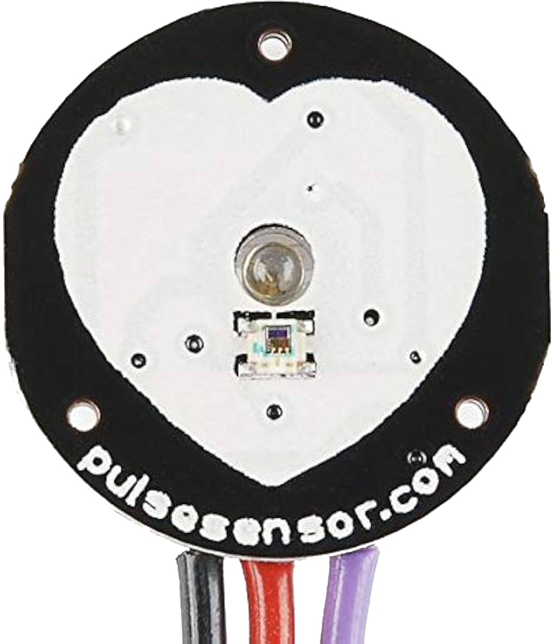
The Pulse Sensor is a device designed to detect and measure the heartbeat of an individual. It operates using photoplethysmography (PPG), a non-invasive optical technique that monitors blood flow changes in the body. This sensor is compact, easy to use, and ideal for applications requiring real-time heart rate monitoring.
Explore Projects Built with Pulse Sensor
Explore Projects Built with Pulse Sensor
Common Applications and Use Cases
- Fitness trackers and wearable health devices
- Medical monitoring systems
- Biofeedback and stress management tools
- Educational projects and DIY electronics
- Integration with microcontrollers like Arduino for heart rate visualization
Technical Specifications
The following table outlines the key technical details of the Pulse Sensor:
| Parameter | Value |
|---|---|
| Operating Voltage | 3.3V to 5V |
| Operating Current | ~4mA |
| Output Signal | Analog (0-1023 for Arduino ADC) |
| Sensor Type | Photoplethysmography (PPG) |
| Dimensions | ~16mm diameter |
| Cable Length | ~24 inches |
Pin Configuration and Descriptions
The Pulse Sensor typically has a 3-pin interface. The pinout is as follows:
| Pin | Name | Description |
|---|---|---|
| 1 | VCC | Power supply pin (3.3V or 5V) |
| 2 | GND | Ground connection |
| 3 | Signal | Analog output signal representing heartbeat data |
Usage Instructions
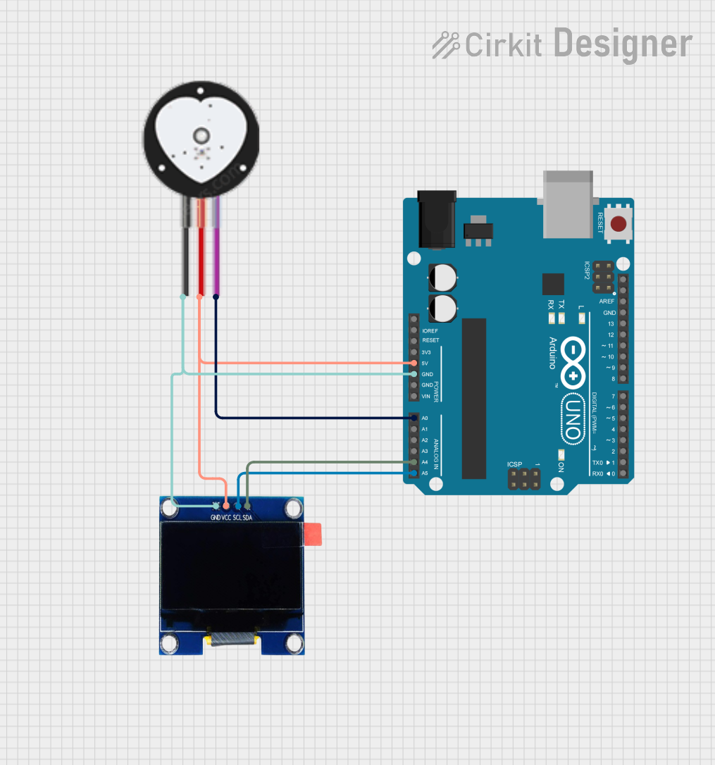
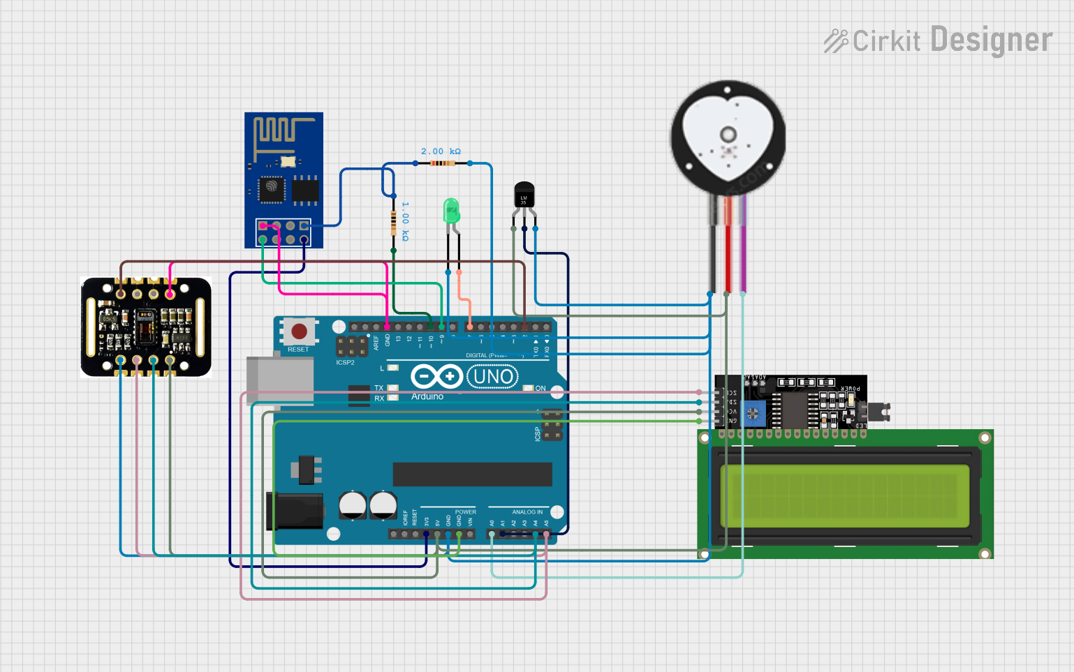
How to Use the Pulse Sensor in a Circuit
Connect the Pins:
- Connect the
VCCpin to the 3.3V or 5V power supply of your microcontroller. - Connect the
GNDpin to the ground of your circuit. - Connect the
Signalpin to an analog input pin on your microcontroller (e.g., A0 on Arduino).
- Connect the
Place the Sensor:
- Attach the sensor to a fingertip or earlobe using the included Velcro strap or clip.
- Ensure the sensor is securely in place for accurate readings.
Read the Signal:
- Use an analog-to-digital converter (ADC) to read the signal from the
Signalpin. - Process the signal to extract heart rate data.
- Use an analog-to-digital converter (ADC) to read the signal from the
Important Considerations and Best Practices
- Avoid excessive movement during measurement to reduce noise and improve accuracy.
- Ensure the sensor is clean and free from dirt or oil for optimal performance.
- Use a low-pass filter in your circuit or software to smooth out the signal.
- If using an Arduino, ensure the
Signalpin is connected to an analog input pin.
Example Code for Arduino UNO
Below is an example code snippet to read and display heart rate data using the Pulse Sensor:
// Include the PulseSensor library (install via Arduino Library Manager)
#include <PulseSensorPlayground.h>

// Define constants for the Pulse Sensor
const int PULSE_PIN = A0;  // Analog pin connected to the Signal pin
const int LED_PIN = 13;    // Onboard LED for heartbeat indication

// Create a PulseSensor object
PulseSensorPlayground pulseSensor;

void setup() {
  Serial.begin(9600);  // Initialize serial communication
  pinMode(LED_PIN, OUTPUT);  // Set LED pin as output

  // Configure the Pulse Sensor
  pulseSensor.analogInput(PULSE_PIN);
  pulseSensor.blinkOnPulse(LED_PIN);  // Blink LED on heartbeat
  pulseSensor.setSerial(Serial);     // Enable serial output for debugging

  // Start the Pulse Sensor
  if (!pulseSensor.begin()) {
    Serial.println("Pulse Sensor initialization failed!");
    while (true);  // Halt execution if initialization fails
  }
}

void loop() {
  // Read the Pulse Sensor
  int heartRate = pulseSensor.getBeatsPerMinute();

  // Check if a valid heart rate is detected
  if (pulseSensor.sawStartOfBeat()) {
    Serial.print("Heart Rate: ");
    Serial.print(heartRate);
    Serial.println(" BPM");  // Print heart rate in beats per minute
  }

  delay(20);  // Small delay for stable readings
}
Notes on the Code
- The
PulseSensorPlaygroundlibrary simplifies the use of the Pulse Sensor. Install it via the Arduino Library Manager. - The onboard LED (pin 13) blinks with each detected heartbeat.
- The heart rate is displayed in beats per minute (BPM) on the Serial Monitor.
Troubleshooting and FAQs
Common Issues and Solutions
No Signal Detected:
- Ensure the sensor is properly connected to the microcontroller.
- Verify that the sensor is securely attached to the measurement site (e.g., fingertip).
Inconsistent Readings:
- Minimize movement during measurement to reduce noise.
- Use a software filter to smooth out the signal.
Sensor Not Working:
- Check the power supply voltage (3.3V or 5V).
- Ensure the
Signalpin is connected to an analog input pin.
LED Not Blinking:
- Verify the
LED_PINis correctly defined in the code. - Check the Pulse Sensor library installation.
- Verify the
FAQs
Q: Can the Pulse Sensor be used with a Raspberry Pi?
A: Yes, but since the Raspberry Pi lacks an onboard ADC, you will need an external ADC module (e.g., MCP3008) to read the analog signal.
Q: How do I clean the Pulse Sensor?
A: Use a soft, damp cloth to gently clean the sensor surface. Avoid using harsh chemicals.
Q: Can the Pulse Sensor measure blood oxygen levels?
A: No, the Pulse Sensor is designed only for heart rate monitoring and does not measure blood oxygen saturation (SpO2).
Q: What is the maximum heart rate the sensor can detect?
A: The sensor can typically detect heart rates up to 220 BPM, depending on the signal quality and processing algorithm.
By following this documentation, you can effectively integrate the Pulse Sensor into your projects for accurate and reliable heart rate monitoring.