How to Use 3.5 inch ESP32-S3 Display module: Examples, Pinouts, and Specs
Introduction
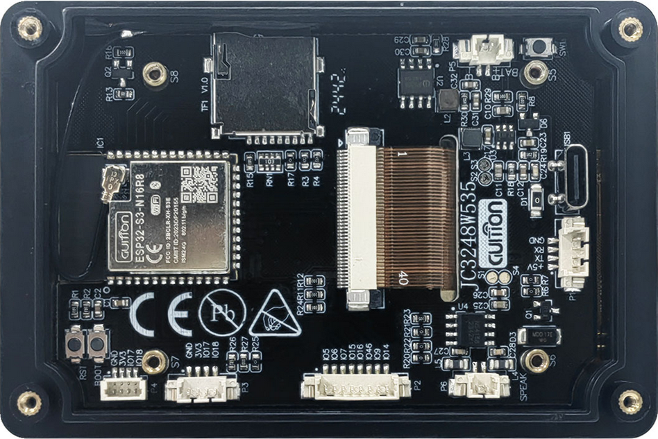
The 3.5 inch ESP32-S3 Display Module (Manufacturer Part ID: JC3248W535C_I_Y) by Shenzhen Jingcai Intelligent is a compact and versatile display module. It features a 3.5-inch touchscreen interface and is powered by the ESP32-S3 microcontroller, which supports both Wi-Fi and Bluetooth connectivity. This module is ideal for creating interactive applications, such as IoT dashboards, smart home interfaces, and portable devices.
Explore Projects Built with 3.5 inch ESP32-S3 Display module


Explore Projects Built with 3.5 inch ESP32-S3 Display module
Common Applications and Use Cases
- IoT control panels and dashboards
- Smart home automation interfaces
- Portable multimedia devices
- Educational and prototyping projects
- Industrial control systems
- Wearable devices with touchscreen functionality
Technical Specifications
Key Technical Details
| Parameter | Specification |
|---|---|
| Display Size | 3.5 inches |
| Resolution | 480 x 320 pixels |
| Touchscreen Type | Capacitive |
| Microcontroller | ESP32-S3 |
| Connectivity | Wi-Fi 802.11 b/g/n, Bluetooth 5.0 |
| Operating Voltage | 3.3V |
| Power Consumption | ~200mA (typical) |
| Interface | SPI |
| Flash Memory | 16MB |
| PSRAM | 8MB |
| Dimensions | 85mm x 55mm x 10mm |
Pin Configuration and Descriptions
The module has a standard pin header for easy integration into circuits. Below is the pinout:
| Pin No. | Pin Name | Description |
|---|---|---|
| 1 | GND | Ground connection |
| 2 | VCC | Power supply input (3.3V) |
| 3 | SCK | SPI Clock |
| 4 | MOSI | SPI Master Out Slave In |
| 5 | MISO | SPI Master In Slave Out |
| 6 | CS | Chip Select for SPI |
| 7 | RST | Reset pin |
| 8 | INT | Interrupt pin for touchscreen events |
| 9 | SDA | I2C Data Line (used for touchscreen communication) |
| 10 | SCL | I2C Clock Line (used for touchscreen communication) |
| 11 | TX | UART Transmit (for debugging or serial communication) |
| 12 | RX | UART Receive (for debugging or serial communication) |
Usage Instructions
How to Use the Component in a Circuit
- Powering the Module: Connect the
VCCpin to a 3.3V power source and theGNDpin to ground. - SPI Communication: Connect the
SCK,MOSI,MISO, andCSpins to the corresponding SPI pins on your microcontroller or development board. - Touchscreen Interface: Use the
SDAandSCLpins for I2C communication to read touchscreen inputs. - Reset and Interrupt: Connect the
RSTpin to a GPIO pin for resetting the module, and theINTpin to a GPIO pin to handle touchscreen interrupts. - Debugging: Use the
TXandRXpins for serial communication to debug or send data.
Important Considerations and Best Practices
- Ensure the power supply is stable and does not exceed 3.3V to avoid damaging the module.
- Use appropriate pull-up resistors for the I2C lines (
SDAandSCL) if not already included in your circuit. - Avoid placing the module near high-frequency noise sources to maintain reliable Wi-Fi and Bluetooth connectivity.
- Use a level shifter if interfacing with a 5V microcontroller to prevent damage to the module's pins.
Example Code for Arduino UNO
Below is an example of how to interface the module with an Arduino UNO using the SPI interface. Note that the ESP32-S3 module can also be programmed directly, but this example assumes the Arduino UNO is used as a host controller.
#include <SPI.h>
#include <Adafruit_GFX.h>
#include <Adafruit_ILI9341.h>

// Define SPI pins for the display
#define TFT_CS   10  // Chip Select pin
#define TFT_RST  9   // Reset pin
#define TFT_DC   8   // Data/Command pin

// Initialize the display object
Adafruit_ILI9341 tft = Adafruit_ILI9341(TFT_CS, TFT_DC, TFT_RST);

void setup() {
  // Initialize serial communication for debugging
  Serial.begin(9600);
  Serial.println("Initializing 3.5 inch ESP32-S3 Display Module...");

  // Initialize the display
  tft.begin();
  tft.setRotation(1); // Set display orientation
  tft.fillScreen(ILI9341_BLACK); // Clear the screen with black color

  // Display a welcome message
  tft.setTextColor(ILI9341_WHITE);
  tft.setTextSize(2);
  tft.setCursor(10, 10);
  tft.println("Hello, World!");
}

void loop() {
  // Example: Draw a rectangle that changes color
  static uint16_t color = ILI9341_RED;
  tft.fillRect(50, 50, 100, 100, color);
  delay(1000);
  color = (color == ILI9341_RED) ? ILI9341_BLUE : ILI9341_RED;
}
Notes on the Code
- The
Adafruit_ILI9341library is used to control the display. Install it via the Arduino Library Manager. - Ensure the SPI pins on the Arduino UNO are connected to the corresponding pins on the module (
SCK,MOSI,MISO, andCS).
Troubleshooting and FAQs
Common Issues and Solutions
Display Not Turning On:
- Verify that the
VCCandGNDpins are properly connected. - Ensure the power supply provides a stable 3.3V.
- Verify that the
Touchscreen Not Responding:
- Check the I2C connections (
SDAandSCL) and ensure pull-up resistors are used if necessary. - Verify that the interrupt pin (
INT) is correctly configured in your code.
- Check the I2C connections (
Wi-Fi or Bluetooth Connectivity Issues:
- Ensure the module is not placed near sources of electromagnetic interference.
- Check your code for proper initialization of the ESP32-S3's Wi-Fi or Bluetooth features.
Flickering or Artifacts on the Display:
- Verify the SPI clock speed in your code. A clock speed of 40MHz or lower is recommended.
- Check for loose or poor connections in the SPI lines.
FAQs
Q: Can I power the module with 5V?
A: No, the module operates at 3.3V. Use a voltage regulator or level shifter if interfacing with a 5V system.
Q: Is the module compatible with other microcontrollers?
A: Yes, the module can be used with any microcontroller that supports SPI and I2C communication, such as Arduino, STM32, or Raspberry Pi.
Q: How do I update the firmware on the ESP32-S3?
A: Use the ESP-IDF or Arduino IDE to upload firmware via the USB interface or UART pins (TX and RX).
Q: Can I use the module outdoors?
A: The module is not weatherproof. Use an appropriate enclosure for outdoor applications.
Q: What is the maximum range for Wi-Fi and Bluetooth?
A: The range depends on environmental factors but typically reaches up to 30 meters indoors and 100 meters outdoors for Wi-Fi.
This concludes the documentation for the 3.5 inch ESP32-S3 Display Module. For further assistance, refer to the manufacturer's datasheet or contact technical support.