How to Use AS5048A magnetic rotary encoder: Examples, Pinouts, and Specs
Introduction
The AS5048A is a high-resolution magnetic rotary encoder manufactured by AM5. It is designed to provide precise angular position measurements by detecting the orientation of a magnetic field. The encoder outputs the position in a digital format, making it ideal for applications requiring accurate rotational feedback.
Explore Projects Built with AS5048A magnetic rotary encoder
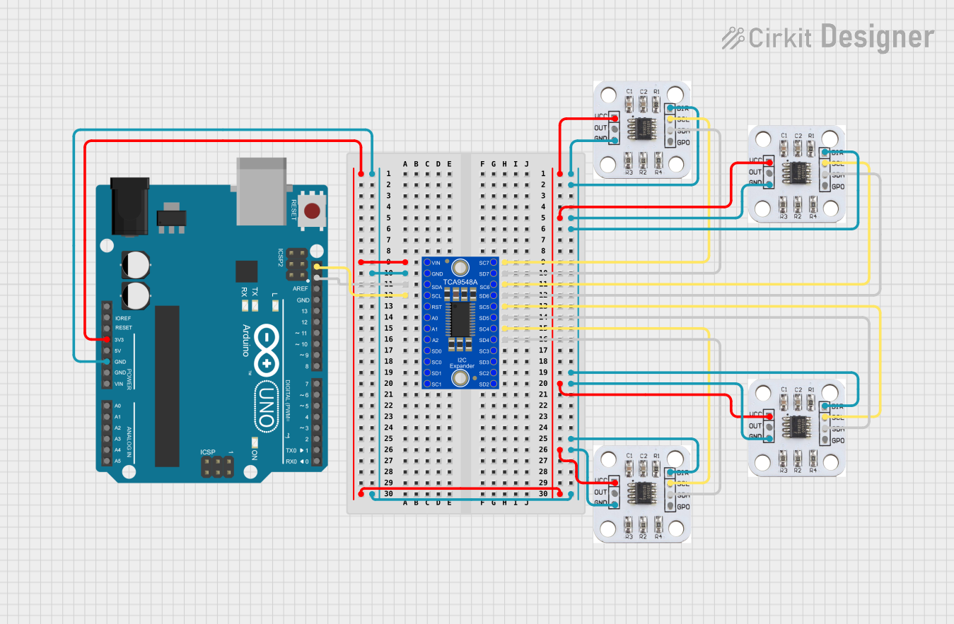


Explore Projects Built with AS5048A magnetic rotary encoder
Common Applications and Use Cases
- Robotics: For joint position sensing and motion control.
- Motor Control: To provide feedback for brushless DC (BLDC) and stepper motors.
- Industrial Automation: For precise positioning in automated systems.
- Consumer Electronics: In devices requiring rotational input or feedback.
- Medical Devices: For applications like robotic surgery or diagnostic equipment.
Technical Specifications
The AS5048A is a versatile and robust encoder with the following key specifications:
| Parameter | Value |
|---|---|
| Supply Voltage (VDD) | 3.3V to 5.0V |
| Current Consumption | 12 mA (typical) |
| Resolution | 14-bit (16,384 steps per revolution) |
| Interface | SPI or PWM |
| Maximum Speed | 30,000 RPM |
| Operating Temperature | -40°C to +150°C |
| Magnetic Field Strength | 30 mT to 70 mT |
| Package | TSSOP-14 |
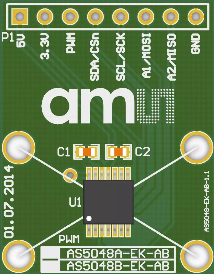
Pin Configuration and Descriptions
The AS5048A comes in a TSSOP-14 package with the following pinout:
| Pin Number | Pin Name | Description |
|---|---|---|
| 1 | VDD | Positive supply voltage (3.3V to 5.0V). |
| 2 | GND | Ground. |
| 3 | CSn | Chip Select (active low) for SPI communication. |
| 4 | CLK | SPI Clock input. |
| 5 | MISO | SPI Master-In-Slave-Out (data output). |
| 6 | MOSI | SPI Master-Out-Slave-In (data input). |
| 7 | PWM | Pulse Width Modulation output for angle data. |
| 8-14 | NC | Not connected (leave floating). |
Usage Instructions
How to Use the AS5048A in a Circuit
- Power Supply: Connect the VDD pin to a 3.3V or 5.0V power source and the GND pin to ground.
- Magnet Placement: Place a diametrically magnetized magnet (e.g., a neodymium magnet) above the encoder chip. Ensure the magnet is centered and within the recommended distance (1-2 mm).
- Communication Interface:
- For SPI: Connect the CSn, CLK, MISO, and MOSI pins to the corresponding SPI pins on your microcontroller.
- For PWM: Use the PWM pin to read the angle data as a duty cycle.
- Bypass Capacitor: Place a 100 nF ceramic capacitor close to the VDD and GND pins for power supply decoupling.
Important Considerations and Best Practices
- Magnet Alignment: Ensure the magnet is properly aligned with the center of the encoder for accurate readings.
- Magnetic Field Strength: Use a magnet with a field strength between 30 mT and 70 mT for optimal performance.
- Noise Filtering: Add a low-pass filter to the PWM output if using the PWM interface.
- SPI Configuration: Configure the SPI interface with the following settings:
- Clock polarity (CPOL): 0
- Clock phase (CPHA): 1
- Data order: MSB first
Example Code for Arduino UNO
Below is an example of how to interface the AS5048A with an Arduino UNO using SPI:
#include <SPI.h>

// Define SPI pins for AS5048A
const int CS_PIN = 10; // Chip Select pin

void setup() {
  // Initialize Serial Monitor
  Serial.begin(9600);

  // Initialize SPI
  SPI.begin();
  pinMode(CS_PIN, OUTPUT);
  digitalWrite(CS_PIN, HIGH); // Set CS high to deselect the device
}

uint16_t readAngle() {
  uint16_t angle = 0;

  // Select the AS5048A
  digitalWrite(CS_PIN, LOW);

  // Send command to read angle (0xFFFF is the command for angle read)
  SPI.transfer16(0xFFFF);

  // Read the 16-bit angle data
  angle = SPI.transfer16(0x0000);

  // Deselect the AS5048A
  digitalWrite(CS_PIN, HIGH);

  // Return the angle value
  return angle & 0x3FFF; // Mask to 14 bits
}

void loop() {
  // Read the angle from the AS5048A
  uint16_t angle = readAngle();

  // Convert angle to degrees (0-360)
  float angleDegrees = (angle * 360.0) / 16384.0;

  // Print the angle to the Serial Monitor
  Serial.print("Angle: ");
  Serial.print(angleDegrees);
  Serial.println(" degrees");

  delay(100); // Wait 100 ms before the next reading
}
Troubleshooting and FAQs
Common Issues and Solutions
No Output or Incorrect Readings:
- Cause: Magnet misalignment or incorrect distance.
- Solution: Ensure the magnet is centered and within 1-2 mm of the encoder.
SPI Communication Fails:
- Cause: Incorrect SPI settings or wiring.
- Solution: Verify the SPI clock polarity, phase, and connections.
Noisy PWM Output:
- Cause: Electrical noise or insufficient filtering.
- Solution: Add a low-pass filter to the PWM output.
Overheating:
- Cause: Excessive current draw or incorrect power supply voltage.
- Solution: Ensure the supply voltage is within the 3.3V to 5.0V range.
FAQs
Q1: Can the AS5048A measure absolute position?
Yes, the AS5048A provides absolute angular position measurements with 14-bit resolution.
Q2: What type of magnet should I use?
Use a diametrically magnetized magnet with a field strength of 30 mT to 70 mT.
Q3: Can I use the AS5048A with a 3.3V microcontroller?
Yes, the AS5048A is compatible with both 3.3V and 5.0V systems.
Q4: What is the maximum rotational speed the AS5048A can handle?
The AS5048A can measure angles accurately at speeds up to 30,000 RPM.