How to Use RS485 V2: Examples, Pinouts, and Specs
Introduction
The RS485 V2 is a standard for serial communication that enables reliable, long-distance data transmission. It supports multiple devices on a single bus, making it ideal for multi-point communication systems. Known for its robustness, RS485 V2 is widely used in industrial applications, where it operates effectively even in noisy environments. Its differential signaling method ensures high immunity to electromagnetic interference (EMI), making it a preferred choice for industrial automation, building management systems, and remote data acquisition.
Explore Projects Built with RS485 V2


Explore Projects Built with RS485 V2
Common Applications:
- Industrial automation and control systems
- Building management systems (e.g., HVAC, lighting control)
- Remote data acquisition and monitoring
- Communication between microcontrollers and sensors
- Long-distance serial communication in noisy environments
Technical Specifications
Key Technical Details:
- Communication Standard: RS485
- Voltage Levels: -7V to +12V (differential signaling)
- Maximum Data Rate: Up to 10 Mbps (depending on cable length)
- Maximum Cable Length: Up to 1200 meters (at lower data rates)
- Number of Devices: Supports up to 32 devices on a single bus (expandable with repeaters)
- Connector Type: Terminal block or DB9 (varies by module)
- Operating Temperature: -40°C to +85°C
- Power Supply: Typically 5V or 3.3V (depending on the module)
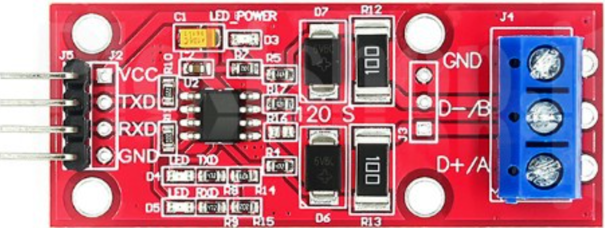
Pin Configuration and Descriptions:
Below is a typical pinout for an RS485 V2 module:
| Pin Name | Description |
|---|---|
| VCC | Power supply input (commonly 5V or 3.3V). |
| GND | Ground connection. |
| A (D+) | Non-inverting data line (positive differential signal). |
| B (D-) | Inverting data line (negative differential signal). |
| RO | Receiver output (data received from the RS485 bus). |
| DI | Driver input (data to be transmitted onto the RS485 bus). |
| DE | Driver enable (controls whether the module transmits or receives data). |
| RE | Receiver enable (active low; enables the receiver when pulled low). |
Note: Pin names and configurations may vary slightly depending on the specific RS485 V2 module. Always refer to the datasheet for your module.
Usage Instructions
How to Use the RS485 V2 in a Circuit:
- Power the Module: Connect the VCC pin to a 5V or 3.3V power source and the GND pin to ground.
- Connect the Data Lines:
- Connect the A (D+) and B (D-) pins to the corresponding lines of the RS485 bus.
- Ensure proper termination resistors (typically 120Ω) are placed at both ends of the bus to prevent signal reflections.
- Control the Module:
- Use the DE pin to enable the driver for transmitting data.
- Use the RE pin (active low) to enable the receiver for receiving data.
- Interface with a Microcontroller:
- Connect the DI pin to the microcontroller's TX pin for transmitting data.
- Connect the RO pin to the microcontroller's RX pin for receiving data.
Important Considerations:
- Termination Resistors: Always use termination resistors at both ends of the RS485 bus to ensure signal integrity.
- Biasing Resistors: Add pull-up and pull-down resistors to the A and B lines to maintain a known idle state when no devices are transmitting.
- Cable Selection: Use twisted-pair cables for the A and B lines to minimize noise and crosstalk.
- Grounding: Ensure all devices on the RS485 bus share a common ground to avoid communication errors.
Example: Connecting RS485 V2 to an Arduino UNO
Below is an example of how to use the RS485 V2 module with an Arduino UNO for communication:
Circuit Connections:
- RS485 V2 Module:
- VCC → 5V on Arduino
- GND → GND on Arduino
- DI → Pin 3 (TX) on Arduino
- RO → Pin 2 (RX) on Arduino
- DE → Pin 4 on Arduino
- RE → Pin 4 on Arduino (tied to DE for simplicity)
Arduino Code:
// Include the SoftwareSerial library for serial communication
#include <SoftwareSerial.h>

// Define RS485 pins
#define RX_PIN 2  // Arduino pin connected to RO (Receiver Output)
#define TX_PIN 3  // Arduino pin connected to DI (Driver Input)
#define DE_RE_PIN 4  // Arduino pin connected to DE and RE (Driver/Receiver Enable)

// Create a SoftwareSerial object
SoftwareSerial RS485Serial(RX_PIN, TX_PIN);

void setup() {
  // Initialize the RS485 serial communication
  RS485Serial.begin(9600);  // Set baud rate to 9600
  pinMode(DE_RE_PIN, OUTPUT);  // Set DE/RE pin as output
  digitalWrite(DE_RE_PIN, LOW);  // Set to receive mode by default

  // Initialize the default serial monitor
  Serial.begin(9600);
  Serial.println("RS485 Communication Initialized");
}

void loop() {
  // Example: Send data over RS485
  digitalWrite(DE_RE_PIN, HIGH);  // Enable transmit mode
  RS485Serial.println("Hello from Arduino!");  // Send data
  delay(100);  // Short delay
  digitalWrite(DE_RE_PIN, LOW);  // Enable receive mode

  // Example: Receive data over RS485
  if (RS485Serial.available()) {
    String receivedData = RS485Serial.readString();  // Read incoming data
    Serial.print("Received: ");
    Serial.println(receivedData);  // Print received data to serial monitor
  }

  delay(1000);  // Wait before next iteration
}
Note: Adjust the baud rate and pin connections as needed for your specific application.
Troubleshooting and FAQs
Common Issues and Solutions:
No Communication Between Devices:
- Cause: Incorrect wiring or missing termination resistors.
- Solution: Double-check the connections and ensure 120Ω termination resistors are installed at both ends of the RS485 bus.
Data Corruption or Noise:
- Cause: Long cable lengths or improper grounding.
- Solution: Use twisted-pair cables, ensure proper grounding, and reduce the baud rate if necessary.
Devices Not Responding:
- Cause: Incorrect DE/RE pin control.
- Solution: Verify that the DE pin is HIGH during transmission and LOW during reception.
Intermittent Communication Failures:
- Cause: Missing or incorrect biasing resistors.
- Solution: Add pull-up and pull-down resistors to the A and B lines to maintain a known idle state.
FAQs:
Q: Can RS485 V2 modules communicate with RS232 devices?
- A: No, RS485 and RS232 use different signaling methods. A converter is required for communication between the two standards.
Q: How many devices can I connect to an RS485 bus?
- A: RS485 supports up to 32 devices on a single bus. This can be expanded using RS485 repeaters.
Q: What is the maximum cable length for RS485 communication?
- A: RS485 can support cable lengths up to 1200 meters at lower data rates. For higher data rates, the maximum length decreases.
Q: Can I use RS485 V2 with a 3.3V microcontroller?
- A: Yes, but ensure the RS485 module supports 3.3V operation or use a level shifter.
By following this documentation, you can effectively integrate the RS485 V2 module into your projects for robust and reliable serial communication.