How to Use STM32WB55RG: Examples, Pinouts, and Specs
Introduction
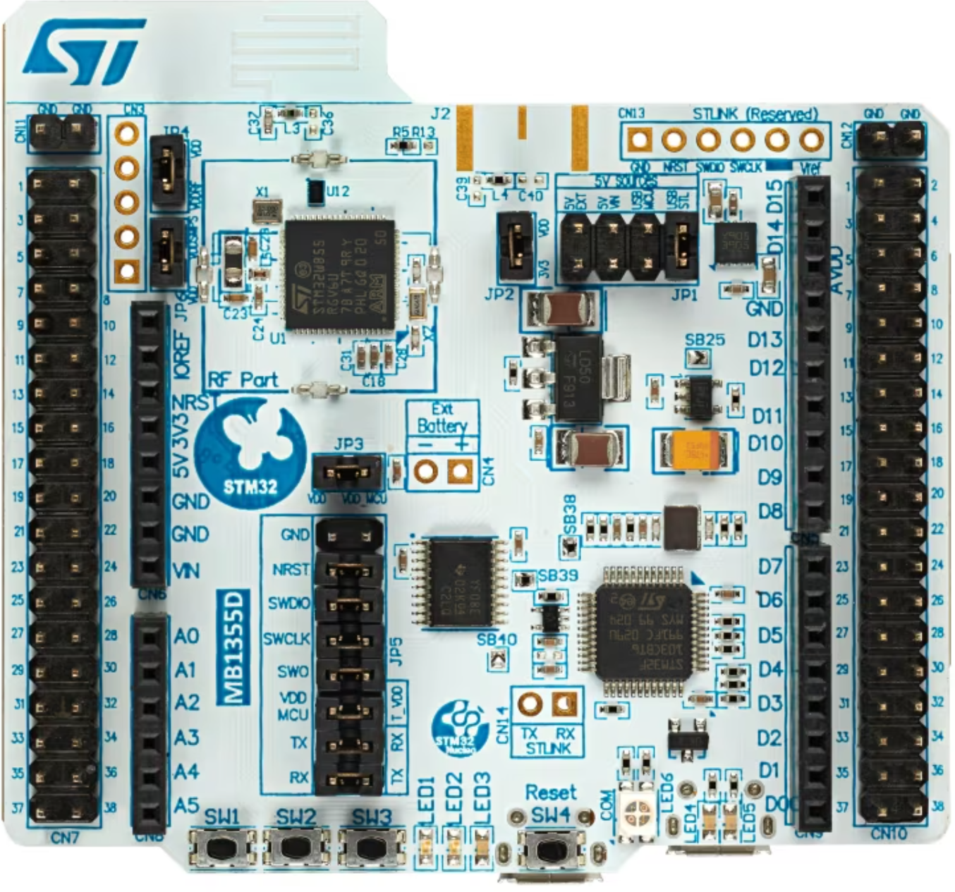
The STM32WB55RG is a dual-core microcontroller developed by STMicroelectronics. It features an ARM Cortex-M4 core for high-performance application processing and an ARM Cortex-M0+ core dedicated to managing low-power tasks. This microcontroller is equipped with Bluetooth 5.0 connectivity, making it an excellent choice for IoT (Internet of Things) applications. It also includes a wide range of peripherals, offering flexibility for various embedded system designs.
Explore Projects Built with STM32WB55RG


Explore Projects Built with STM32WB55RG
Common Applications and Use Cases
- IoT devices and smart home applications
- Wearable technology
- Industrial automation and control systems
- Medical devices
- Wireless sensor networks
- Asset tracking and monitoring systems
Technical Specifications
Key Technical Details
| Parameter | Value |
|---|---|
| Core Architecture | ARM Cortex-M4 (main) + ARM Cortex-M0+ (RF) |
| Operating Frequency | Up to 64 MHz (Cortex-M4) |
| Flash Memory | 1 MB |
| RAM | 256 KB |
| Bluetooth Version | Bluetooth 5.0 |
| Operating Voltage | 1.7 V to 3.6 V |
| GPIO Pins | Up to 43 |
| Communication Interfaces | I2C, SPI, UART, USB, CAN, and more |
| ADC Resolution | 12-bit |
| Operating Temperature Range | -40°C to +85°C |
| Package Type | LQFP64 (64-pin) |
Pin Configuration and Descriptions
The STM32WB55RG comes in a 64-pin LQFP package. Below is a summary of key pins and their functions:
| Pin Number | Pin Name | Functionality |
|---|---|---|
| 1 | VDD | Power supply |
| 2 | VSS | Ground |
| 10 | PA0 | GPIO, ADC input, or external interrupt |
| 20 | PB6 | I2C1_SCL or GPIO |
| 30 | PC13 | GPIO or wake-up pin |
| 40 | PA9 | USART1_TX or GPIO |
| 50 | PB3 | SPI1_SCK or GPIO |
| 60 | PA15 | GPIO or external interrupt |
| 64 | NRST | Reset pin |
For a complete pinout, refer to the STM32WB55RG datasheet provided by STMicroelectronics.
Usage Instructions
How to Use the STM32WB55RG in a Circuit
- Power Supply: Connect the VDD pin to a stable power source (1.7 V to 3.6 V) and the VSS pin to ground.
- Clock Configuration: Use an external crystal oscillator or the internal clock for system timing. Ensure proper configuration in the firmware.
- Programming: Use an ST-LINK programmer/debugger to upload firmware via the SWD (Serial Wire Debug) interface.
- Peripherals: Configure the desired peripherals (e.g., UART, SPI, I2C) in the firmware using STM32CubeMX or direct register programming.
- Bluetooth: Enable and configure the Bluetooth stack using the provided STMicroelectronics libraries.
Important Considerations and Best Practices
- Power Management: Utilize the low-power modes of the Cortex-M0+ core to optimize energy consumption in battery-powered applications.
- Decoupling Capacitors: Place decoupling capacitors (e.g., 0.1 µF) close to the VDD pins to reduce noise and ensure stable operation.
- Firmware Development: Use the STM32CubeIDE or Keil MDK for firmware development. Leverage the STM32 HAL (Hardware Abstraction Layer) for easier peripheral configuration.
- Bluetooth Configuration: Use the ST BLE stack and ensure proper antenna design for optimal wireless performance.
Example Code for Arduino UNO Integration
Although the STM32WB55RG is not directly compatible with Arduino UNO, it can communicate with an Arduino via UART. Below is an example of how to send data from the STM32WB55RG to an Arduino UNO:
STM32WB55RG Code (Using HAL Library):
#include "stm32wbxx_hal.h"

// UART handle declaration
UART_HandleTypeDef huart1;

void SystemClock_Config(void);
void MX_USART1_UART_Init(void);

int main(void) {
    HAL_Init(); // Initialize the HAL Library
    SystemClock_Config(); // Configure the system clock
    MX_USART1_UART_Init(); // Initialize UART1

    char message[] = "Hello from STM32WB55RG!\r\n";

    while (1) {
        // Transmit message via UART1
        HAL_UART_Transmit(&huart1, (uint8_t *)message, sizeof(message) - 1, HAL_MAX_DELAY);
        HAL_Delay(1000); // Wait for 1 second
    }
}

// UART1 initialization function
void MX_USART1_UART_Init(void) {
    huart1.Instance = USART1;
    huart1.Init.BaudRate = 9600;
    huart1.Init.WordLength = UART_WORDLENGTH_8B;
    huart1.Init.StopBits = UART_STOPBITS_1;
    huart1.Init.Parity = UART_PARITY_NONE;
    huart1.Init.Mode = UART_MODE_TX_RX;
    huart1.Init.HwFlowCtl = UART_HWCONTROL_NONE;
    huart1.Init.OverSampling = UART_OVERSAMPLING_16;
    HAL_UART_Init(&huart1);
}
Arduino UNO Code:
void setup() {
  Serial.begin(9600); // Initialize serial communication at 9600 baud
}

void loop() {
  if (Serial.available()) {
    // Read data from STM32WB55RG and print to Serial Monitor
    String data = Serial.readString();
    Serial.println("Received: " + data);
  }
}
Troubleshooting and FAQs
Common Issues and Solutions
Microcontroller Not Powering On:
- Ensure the VDD and VSS pins are correctly connected.
- Verify the power supply voltage is within the specified range (1.7 V to 3.6 V).
Bluetooth Not Working:
- Check the antenna design and placement.
- Ensure the Bluetooth stack is correctly initialized in the firmware.
UART Communication Fails:
- Verify the baud rate and other UART settings match on both devices.
- Check the physical connections between the STM32WB55RG and the external device.
Programming Issues:
- Ensure the ST-LINK programmer is properly connected.
- Update the ST-LINK firmware and STM32CubeIDE to the latest versions.
FAQs
Q: Can the STM32WB55RG operate in low-power mode?
A: Yes, the Cortex-M0+ core is optimized for low-power tasks, and the microcontroller supports multiple low-power modes.
Q: Is the STM32WB55RG compatible with Arduino libraries?
A: No, the STM32WB55RG uses its own development ecosystem (STM32CubeMX, STM32CubeIDE). However, it can communicate with Arduino boards via standard interfaces like UART, SPI, or I2C.
Q: How do I update the Bluetooth firmware?
A: Use the ST BLE stack and follow the firmware update procedure outlined in the STM32WB55RG reference manual.
For further details, refer to the official STM32WB55RG datasheet and user manual provided by STMicroelectronics.