How to Use retroclick: Examples, Pinouts, and Specs
Introduction
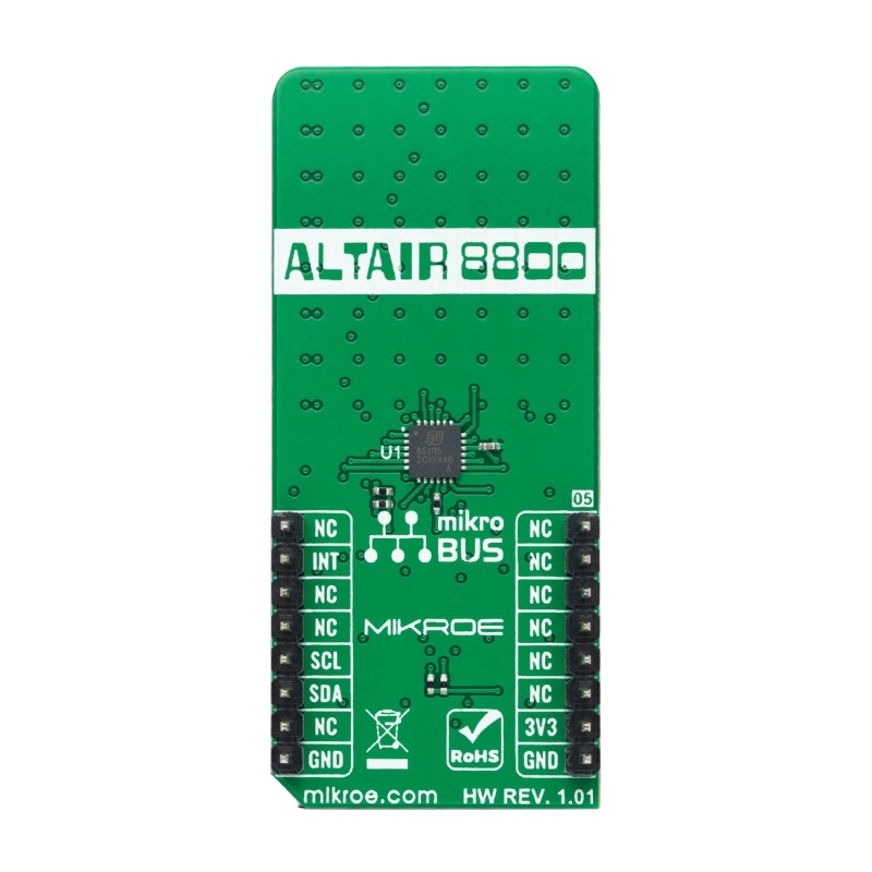
The Retroclick is a tactile switch designed to replicate the feel and aesthetic of vintage electronic devices. It provides a satisfying "click" feedback when pressed, making it ideal for applications where user interaction and nostalgia are key. The Retroclick is commonly used in custom keyboards, retro-style gaming consoles, audio equipment, and DIY electronics projects. Its robust design and unique tactile response make it a favorite among hobbyists and professionals alike.
Explore Projects Built with retroclick


Explore Projects Built with retroclick
Technical Specifications
The Retroclick is a simple yet versatile component. Below are its key technical details:
General Specifications
| Parameter | Value |
|---|---|
| Operating Voltage | 3.3V to 5V |
| Maximum Current Rating | 50mA |
| Contact Resistance | ≤ 100mΩ |
| Insulation Resistance | ≥ 100MΩ at 500V DC |
| Operating Temperature | -20°C to +70°C |
| Actuation Force | 50g to 70g |
| Lifespan | 1,000,000 actuations |
Pin Configuration and Descriptions
The Retroclick typically has two or four pins, depending on the model. Below is the pin configuration for the most common 4-pin variant:
| Pin Number | Description |
|---|---|
| 1 | Switch Terminal 1 (Input) |
| 2 | Switch Terminal 2 (Output) |
| 3 | Switch Terminal 1 (Duplicate) |
| 4 | Switch Terminal 2 (Duplicate) |
Note: Pins 1 and 3 are internally connected, as are pins 2 and 4. This redundancy ensures a stable connection in various mounting configurations.
Usage Instructions
How to Use the Retroclick in a Circuit
- Identify the Pins: Use a multimeter to confirm the continuity between the pins. Pins 1 and 3 are connected, as are pins 2 and 4.
- Connect to Power and Load:
- Connect one terminal (e.g., Pin 1) to the power source or signal input.
- Connect the other terminal (e.g., Pin 2) to the load or signal output.
- Debounce the Switch: To avoid erratic behavior caused by mechanical bouncing, use a capacitor (e.g., 0.1µF) or a software debounce algorithm in your microcontroller code.
- Test the Circuit: Press the Retroclick to ensure proper operation. You should hear a tactile "click" and observe the expected behavior in your circuit.
Important Considerations and Best Practices
- Mounting: Ensure the Retroclick is securely mounted on the PCB or panel to prevent movement during operation.
- Voltage and Current Limits: Do not exceed the specified voltage (5V) or current (50mA) to avoid damaging the switch.
- Debouncing: Always implement debouncing to ensure reliable operation in digital circuits.
- Aesthetic Placement: For retro-themed projects, consider the placement of the Retroclick to enhance the overall design.
Example: Using the Retroclick with an Arduino UNO
Below is an example of how to use the Retroclick with an Arduino UNO to toggle an LED:
// Define pin connections
const int retroclickPin = 2; // Retroclick connected to digital pin 2
const int ledPin = 13;       // LED connected to digital pin 13

// Variable to store the LED state
bool ledState = false;

// Variable to store the last button state
bool lastButtonState = LOW;

// Debounce timing variables
unsigned long lastDebounceTime = 0;
const unsigned long debounceDelay = 50; // 50ms debounce delay

void setup() {
  pinMode(retroclickPin, INPUT_PULLUP); // Set Retroclick pin as input with pull-up
  pinMode(ledPin, OUTPUT);             // Set LED pin as output
}

void loop() {
  // Read the current state of the Retroclick
  bool currentButtonState = digitalRead(retroclickPin);

  // Check if the button state has changed
  if (currentButtonState != lastButtonState) {
    lastDebounceTime = millis(); // Reset debounce timer
  }

  // If the debounce delay has passed and the button state is stable
  if ((millis() - lastDebounceTime) > debounceDelay) {
    // If the button state is HIGH (pressed)
    if (currentButtonState == LOW && lastButtonState == HIGH) {
      ledState = !ledState; // Toggle the LED state
      digitalWrite(ledPin, ledState); // Update the LED
    }
  }

  // Update the last button state
  lastButtonState = currentButtonState;
}
Explanation of the Code:
- The Retroclick is connected to pin 2 of the Arduino UNO with an internal pull-up resistor enabled.
- The LED is connected to pin 13.
- A debounce algorithm ensures that mechanical bouncing does not cause erratic behavior.
- Pressing the Retroclick toggles the LED on and off.
Troubleshooting and FAQs
Common Issues and Solutions
The Retroclick does not respond when pressed:
- Ensure the switch is properly connected to the circuit.
- Verify the voltage and current levels are within the specified range.
- Check for loose connections or cold solder joints.
Erratic behavior when pressing the switch:
- Implement a debounce circuit or software debounce algorithm.
- Check for noise in the power supply and add a decoupling capacitor if necessary.
The tactile feedback feels weak or inconsistent:
- Ensure the Retroclick is not damaged or worn out. Replace if necessary.
- Verify that the switch is securely mounted and not under mechanical stress.
FAQs
Q: Can the Retroclick handle AC signals?
A: The Retroclick is primarily designed for low-voltage DC applications. Using it with AC signals is not recommended unless the voltage and current are within the specified limits.
Q: How do I clean a Retroclick switch?
A: Use compressed air to remove dust and debris. Avoid using liquids or solvents, as they may damage the internal components.
Q: Can I use the Retroclick in outdoor applications?
A: The Retroclick is not weatherproof. For outdoor use, consider enclosing it in a weather-resistant housing.
By following this documentation, you can effectively integrate the Retroclick into your projects and troubleshoot any issues that arise.