Cirkit Designer Logo
Cirkit Designer
Your all-in-one circuit design IDE
Home / 
Component Documentation

How to Use mcudev_tft1.44: Examples, Pinouts, and Specs

Image of mcudev_tft1.44
Cirkit Designer LogoDesign with mcudev_tft1.44 in Cirkit Designer

Introduction

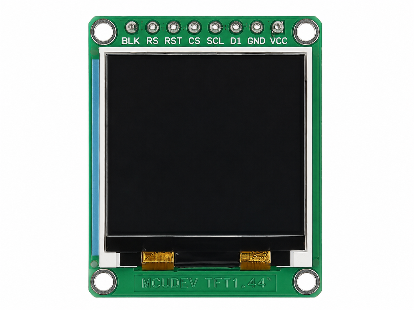
The MCUDEV_TFT1.44 is a compact 1.44-inch TFT display module designed for use in microcontroller-based applications. With a resolution of 128x128 pixels, this module is ideal for displaying graphics, text, and simple animations in embedded systems. It features a vibrant color display and is commonly used in projects requiring a small, low-power graphical interface.

Explore Projects Built with mcudev_tft1.44

Use Cirkit Designer to design, explore, and prototype these projects online. Some projects support real-time simulation. Click "Open Project" to start designing instantly!
ESP32C3-Based Thermal Imaging Camera with TFT Display
Image of MLX90640-XIAO-ESP32-1.3: A project utilizing mcudev_tft1.44 in a practical application
This circuit connects a 1.3 inch TFT Module 240×240 ST7789 display, a GY-MCU90640 thermal camera module, and a XIAO ESP32C3 microcontroller to create a thermal imaging system. The ESP32C3 microcontroller is programmed to read temperature data from the thermal camera, process it, and display a visual representation of the temperature distribution on the TFT screen. The circuit is designed for applications requiring thermal monitoring, such as detecting heat sources or monitoring temperature variations in an environment.
Cirkit Designer LogoOpen Project in Cirkit Designer
RTL8720DN-Based Interactive Button-Controlled TFT Display
Image of coba-coba: A project utilizing mcudev_tft1.44 in a practical application
This circuit features an RTL8720DN microcontroller interfaced with a China ST7735S 160x128 TFT LCD display and four pushbuttons. The microcontroller reads the states of the pushbuttons and displays their statuses on the TFT LCD, providing a visual feedback system for button presses.
Cirkit Designer LogoOpen Project in Cirkit Designer
Arduino UNO and ILI9341 TFT Display Interactive Graphics Demo
Image of CE Test ili9341: A project utilizing mcudev_tft1.44 in a practical application
This circuit interfaces an Arduino UNO with an ILI9341 TFT display using two bi-directional logic level converters to manage voltage differences. The Arduino runs a program to test various graphical functions on the TFT display, demonstrating its capabilities through a series of visual benchmarks.
Cirkit Designer LogoOpen Project in Cirkit Designer
ESP32-Based Health Monitoring System with TFT Display and RTC
Image of RemindeRx Circuit Design: A project utilizing mcudev_tft1.44 in a practical application
This circuit features an ESP32 microcontroller interfaced with an ILI9341 TFT display, a DS3231 RTC module, and a MAX30102 sensor for health monitoring. The ESP32 handles display updates and sensor data acquisition, while the ULN2003 driver controls a 28BYJ-48 stepper motor. The setup is designed for a health monitoring system with a graphical user interface.
Cirkit Designer LogoOpen Project in Cirkit Designer

Explore Projects Built with mcudev_tft1.44

Use Cirkit Designer to design, explore, and prototype these projects online. Some projects support real-time simulation. Click "Open Project" to start designing instantly!
Image of MLX90640-XIAO-ESP32-1.3: A project utilizing mcudev_tft1.44 in a practical application
ESP32C3-Based Thermal Imaging Camera with TFT Display
This circuit connects a 1.3 inch TFT Module 240×240 ST7789 display, a GY-MCU90640 thermal camera module, and a XIAO ESP32C3 microcontroller to create a thermal imaging system. The ESP32C3 microcontroller is programmed to read temperature data from the thermal camera, process it, and display a visual representation of the temperature distribution on the TFT screen. The circuit is designed for applications requiring thermal monitoring, such as detecting heat sources or monitoring temperature variations in an environment.
Cirkit Designer LogoOpen Project in Cirkit Designer
Image of coba-coba: A project utilizing mcudev_tft1.44 in a practical application
RTL8720DN-Based Interactive Button-Controlled TFT Display
This circuit features an RTL8720DN microcontroller interfaced with a China ST7735S 160x128 TFT LCD display and four pushbuttons. The microcontroller reads the states of the pushbuttons and displays their statuses on the TFT LCD, providing a visual feedback system for button presses.
Cirkit Designer LogoOpen Project in Cirkit Designer
Image of CE Test ili9341: A project utilizing mcudev_tft1.44 in a practical application
Arduino UNO and ILI9341 TFT Display Interactive Graphics Demo
This circuit interfaces an Arduino UNO with an ILI9341 TFT display using two bi-directional logic level converters to manage voltage differences. The Arduino runs a program to test various graphical functions on the TFT display, demonstrating its capabilities through a series of visual benchmarks.
Cirkit Designer LogoOpen Project in Cirkit Designer
Image of RemindeRx Circuit Design: A project utilizing mcudev_tft1.44 in a practical application
ESP32-Based Health Monitoring System with TFT Display and RTC
This circuit features an ESP32 microcontroller interfaced with an ILI9341 TFT display, a DS3231 RTC module, and a MAX30102 sensor for health monitoring. The ESP32 handles display updates and sensor data acquisition, while the ULN2003 driver controls a 28BYJ-48 stepper motor. The setup is designed for a health monitoring system with a graphical user interface.
Cirkit Designer LogoOpen Project in Cirkit Designer

Common Applications

  • Wearable devices
  • IoT dashboards
  • Portable measurement tools
  • Educational and hobbyist projects
  • Small graphical user interfaces (GUIs) for embedded systems

Technical Specifications

The following table outlines the key technical details of the MCUDEV_TFT1.44 module:

Parameter Value
Display Type TFT (Thin Film Transistor)
Screen Size 1.44 inches
Resolution 128x128 pixels
Color Depth 65K colors (16-bit RGB)
Interface Type SPI (Serial Peripheral Interface)
Operating Voltage 3.3V (logic level)
Backlight Voltage 3.3V
Current Consumption ~20mA (typical)
Controller IC ST7735
Dimensions 27mm x 27mm x 4.5mm

Pin Configuration

The MCUDEV_TFT1.44 module has an 8-pin interface. The table below describes each pin:

Pin Name Description
1 GND Ground connection
2 VCC Power supply (3.3V)
3 SCL Serial Clock (SPI clock input)
4 SDA Serial Data (SPI data input)
5 RES Reset pin (active low)
6 DC Data/Command control pin
7 CS Chip Select (active low)
8 BLK Backlight control (connect to 3.3V for always on)

Usage Instructions

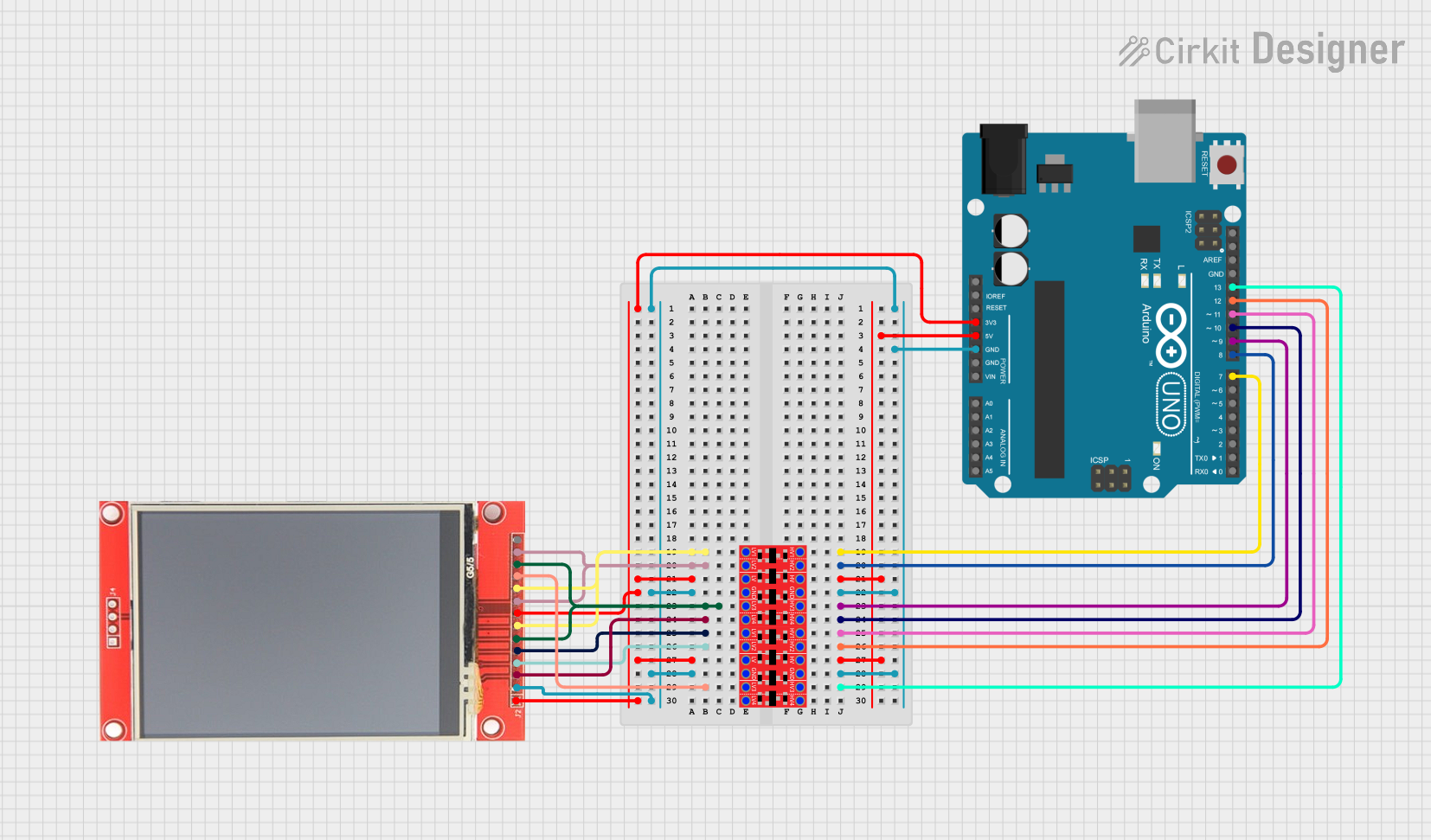
Connecting the MCUDEV_TFT1.44 to a Microcontroller

To use the MCUDEV_TFT1.44 module, connect it to a microcontroller such as an Arduino UNO. Below is a typical wiring configuration:

TFT Pin Arduino UNO Pin
GND GND
VCC 3.3V
SCL D13 (SCK)
SDA D11 (MOSI)
RES D8
DC D9
CS D10
BLK 3.3V

Example Code for Arduino UNO

The following Arduino sketch demonstrates how to initialize and display basic graphics on the MCUDEV_TFT1.44 module using the Adafruit GFX and Adafruit ST7735 libraries.

#include <Adafruit_GFX.h>    // Core graphics library
#include <Adafruit_ST7735.h> // Library for ST7735 controller
#include <SPI.h>             // SPI library

// Define TFT pins
#define TFT_CS   10  // Chip Select pin
#define TFT_RST  8   // Reset pin
#define TFT_DC   9   // Data/Command pin

// Initialize the display object
Adafruit_ST7735 tft = Adafruit_ST7735(TFT_CS, TFT_DC, TFT_RST);

void setup() {
  // Initialize the TFT display
  tft.initR(INITR_144GREENTAB); // Use the 1.44" green tab initialization
  tft.fillScreen(ST77XX_BLACK); // Clear the screen with black color

  // Display a message
  tft.setTextColor(ST77XX_WHITE); // Set text color to white
  tft.setTextSize(1);             // Set text size to 1
  tft.setCursor(10, 10);          // Set cursor position
  tft.println("Hello, World!");   // Print text to the screen

  // Draw a red rectangle
  tft.fillRect(20, 30, 50, 50, ST77XX_RED);
}

void loop() {
  // Nothing to do here
}

Important Considerations

  1. Voltage Levels: Ensure that the logic level of your microcontroller matches the 3.3V requirement of the display. If using a 5V microcontroller (e.g., Arduino UNO), use level shifters or voltage dividers for the SPI pins.
  2. Backlight Control: The backlight pin (BLK) can be connected to a PWM pin on the microcontroller for brightness control.
  3. Library Compatibility: Use the Adafruit GFX and Adafruit ST7735 libraries for easy integration and access to advanced graphics functions.

Troubleshooting and FAQs

Common Issues

  1. No Display Output
    • Solution: Verify all connections, especially the SPI pins (SCL, SDA, CS, DC, RES). Ensure the power supply is stable and at 3.3V.
  2. Flickering or Unstable Display
    • Solution: Check for loose connections or poor solder joints. Ensure the SPI clock speed is not too high (try reducing it in the library settings).
  3. Incorrect Colors or Graphics
    • Solution: Confirm that the correct initialization code (INITR_144GREENTAB) is used for the display.

FAQs

  1. Can I use this display with a 5V microcontroller?
    • Yes, but you must use level shifters or voltage dividers to step down the 5V logic signals to 3.3V.
  2. What is the maximum SPI clock speed supported?
    • The ST7735 controller typically supports SPI clock speeds up to 15 MHz. However, for stability, it is recommended to use a lower speed (e.g., 4 MHz).
  3. Can I control the backlight brightness?
    • Yes, connect the BLK pin to a PWM-capable pin on your microcontroller and use analogWrite() to adjust brightness.

This concludes the documentation for the MCUDEV_TFT1.44 module.