How to Use XL4015 5A DC-DC Step Down Adjustable 4-38V to 1.25-36V - Kunkune: Examples, Pinouts, and Specs
Introduction
The XL4015 is a high-efficiency DC-DC buck converter designed to step down input voltage from a range of 4-38V to a lower, adjustable output voltage between 1.25V and 36V. It supports a maximum output current of 5A, making it suitable for a wide range of power supply applications. This module is widely used in battery charging, LED drivers, and regulated power supplies for electronic devices.
Explore Projects Built with XL4015 5A DC-DC Step Down Adjustable 4-38V to 1.25-36V - Kunkune


Explore Projects Built with XL4015 5A DC-DC Step Down Adjustable 4-38V to 1.25-36V - Kunkune
Common Applications
- Battery charging circuits (e.g., lithium-ion, lead-acid batteries)
- LED lighting systems
- Adjustable power supplies
- Voltage regulation for microcontrollers and other low-voltage devices
- Solar power systems
Technical Specifications
Key Specifications
| Parameter | Value |
|---|---|
| Input Voltage Range | 4V to 38V |
| Output Voltage Range | 1.25V to 36V (adjustable) |
| Maximum Output Current | 5A |
| Output Power | Up to 75W (depending on input/output voltage and cooling) |
| Efficiency | Up to 96% |
| Switching Frequency | 180 kHz |
| Voltage Regulation | ±0.5% |
| Load Regulation | ±0.5% |
| Operating Temperature | -40°C to +85°C |
| Dimensions | 51mm x 26mm x 14mm |
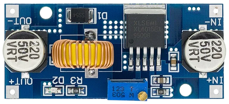
Pin Configuration and Descriptions
| Pin Name | Description |
|---|---|
| VIN+ | Positive input voltage terminal (4V to 38V). Connect to the power source. |
| VIN- | Negative input voltage terminal. Connect to the ground of the power source. |
| VOUT+ | Positive output voltage terminal (1.25V to 36V). Connect to the load. |
| VOUT- | Negative output voltage terminal. Connect to the ground of the load. |
| ADJ | Adjustable potentiometer to set the output voltage. |
Usage Instructions
How to Use the XL4015 in a Circuit
Connect the Input Voltage:
- Connect the positive terminal of the power source to
VIN+. - Connect the ground of the power source to
VIN-. - Ensure the input voltage is within the range of 4V to 38V.
- Connect the positive terminal of the power source to
Connect the Output Load:
- Connect the positive terminal of the load to
VOUT+. - Connect the ground of the load to
VOUT-.
- Connect the positive terminal of the load to
Adjust the Output Voltage:
- Use the onboard potentiometer labeled
ADJto set the desired output voltage. - Turn the potentiometer clockwise to increase the output voltage and counterclockwise to decrease it.
- Use a multimeter to measure the output voltage while adjusting.
- Use the onboard potentiometer labeled
Verify Connections:
- Double-check all connections to ensure proper polarity and secure wiring.
Power On:
- Turn on the power source and verify the output voltage and current using a multimeter.
Important Considerations and Best Practices
- Heat Dissipation: The XL4015 module can generate heat under high current loads. Use a heatsink or active cooling (e.g., a fan) for loads exceeding 3A to prevent overheating.
- Input Voltage Margin: Ensure the input voltage is at least 1.5V higher than the desired output voltage for proper operation.
- Current Limitation: Do not exceed the maximum output current of 5A to avoid damaging the module.
- Short Circuit Protection: The module does not have built-in short circuit protection. Use an external fuse or circuit breaker for safety.
- Ripple Reduction: Add a capacitor (e.g., 100µF) across the output terminals to reduce voltage ripple for sensitive applications.
Example: Using XL4015 with Arduino UNO
The XL4015 can be used to power an Arduino UNO by stepping down a higher voltage (e.g., 12V) to 5V. Below is an example circuit and code:
Circuit Connections
- Connect a 12V power source to
VIN+andVIN-. - Adjust the output voltage to 5V using the potentiometer.
- Connect
VOUT+to the Arduino UNO's 5V pin. - Connect
VOUT-to the Arduino UNO's GND pin.
Example Code
// Example code to blink an LED using Arduino UNO powered by XL4015
// Ensure the XL4015 output is set to 5V before connecting to the Arduino

const int ledPin = 13; // Pin connected to the onboard LED

void setup() {
  pinMode(ledPin, OUTPUT); // Set the LED pin as an output
}

void loop() {
  digitalWrite(ledPin, HIGH); // Turn the LED on
  delay(1000);                // Wait for 1 second
  digitalWrite(ledPin, LOW);  // Turn the LED off
  delay(1000);                // Wait for 1 second
}
Troubleshooting and FAQs
Common Issues and Solutions
| Issue | Possible Cause | Solution |
|---|---|---|
| No output voltage | Incorrect wiring or loose connections | Verify all connections and polarity. |
| Output voltage not adjustable | Faulty potentiometer or incorrect setup | Check the potentiometer and connections. |
| Module overheating | High current load or poor ventilation | Add a heatsink or active cooling. |
| Output voltage fluctuates | Insufficient input voltage or noise | Ensure input voltage is stable and add a capacitor. |
| Arduino not powering on | Incorrect output voltage | Verify the output voltage is set to 5V. |
FAQs
Can the XL4015 be used to charge batteries?
- Yes, the XL4015 can be used for battery charging. However, ensure the output voltage and current are set according to the battery's specifications.
What is the maximum power output of the XL4015?
- The maximum power output is 75W, but this depends on proper cooling and input/output voltage conditions.
Does the XL4015 have overcurrent protection?
- No, the module does not have built-in overcurrent protection. Use an external fuse for safety.
Can I use the XL4015 with a solar panel?
- Yes, the XL4015 can step down the voltage from a solar panel. Ensure the input voltage is within the module's range.
By following this documentation, you can effectively use the XL4015 DC-DC step-down converter in your projects.