
How to Use Kingbright TC07-11 5x7 LED Matrix (Column Cathode): Examples, Pinouts, and Specs

 Design with Kingbright TC07-11 5x7 LED Matrix (Column Cathode) in Cirkit Designer
Introduction
The Kingbright TC07-11 is a 5x7 LED matrix display designed for visual output in a variety of applications. It features a column cathode configuration, which allows for efficient control of individual LEDs within the grid. This component is ideal for creating alphanumeric displays, simple graphics, and other visual indicators in embedded systems and electronic projects.
Explore Projects Built with Kingbright TC07-11 5x7 LED Matrix (Column Cathode)
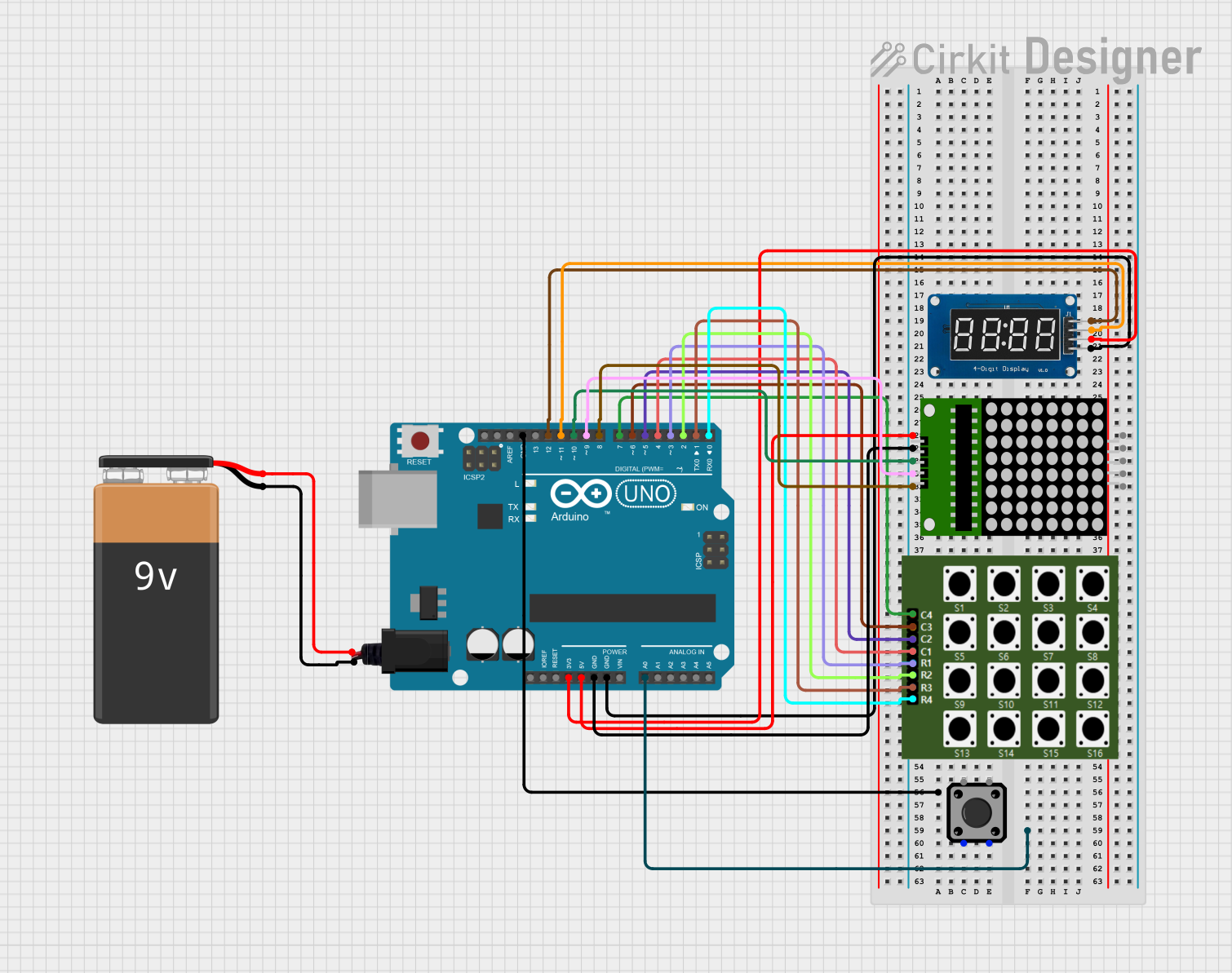 Open Project in Cirkit Designer
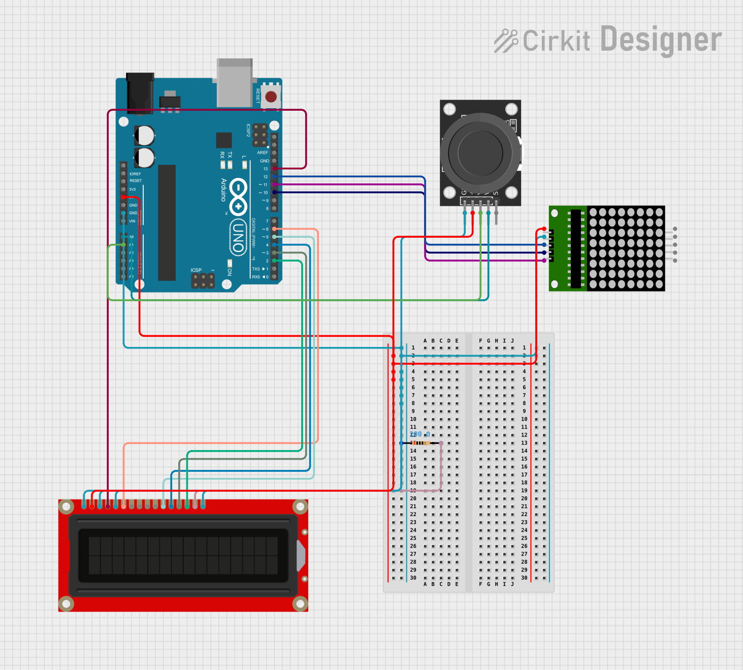 Open Project in Cirkit Designer
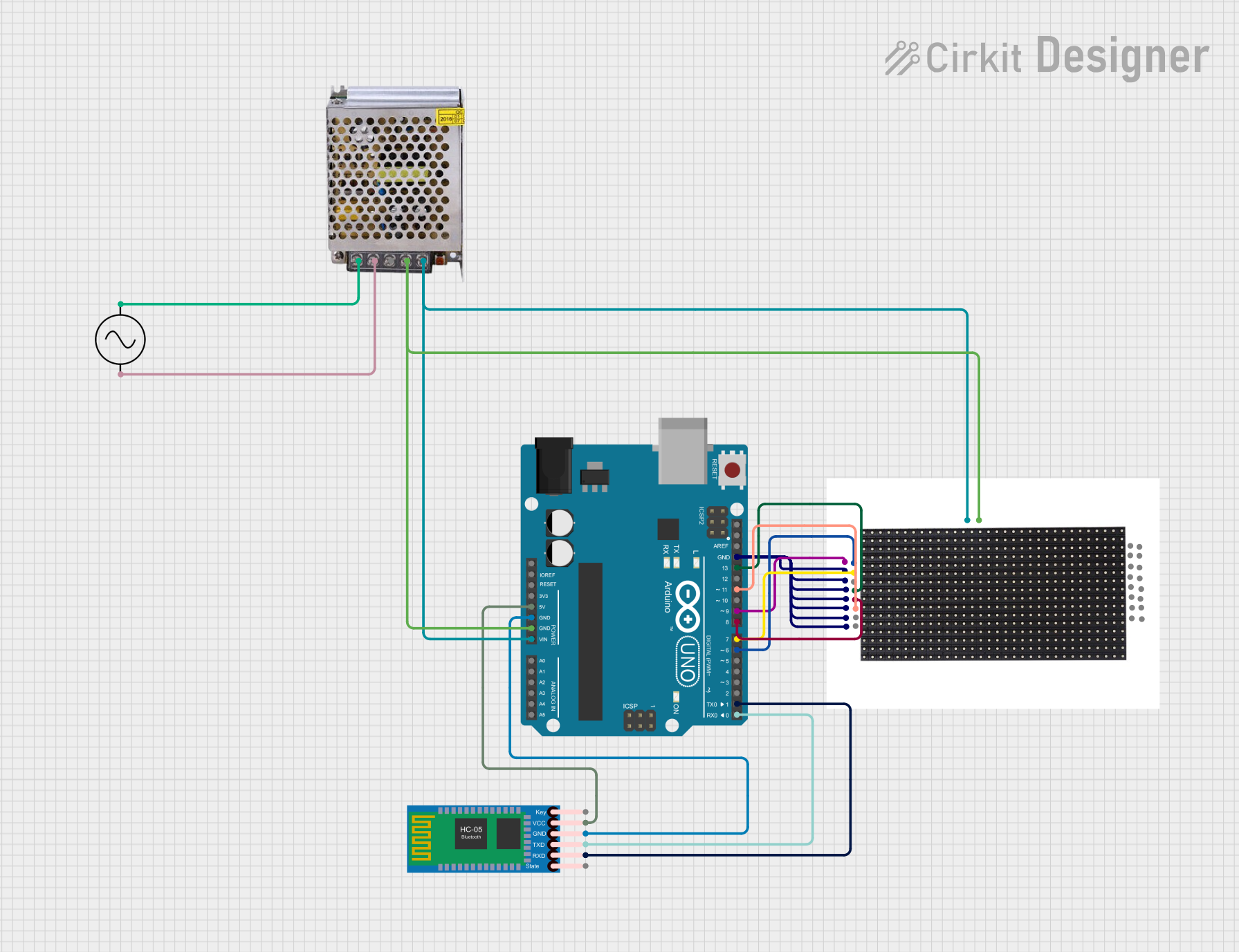 Open Project in Cirkit Designer
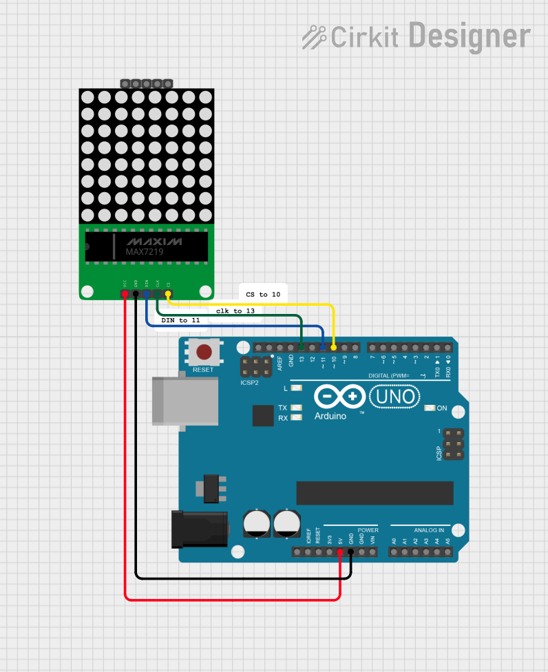 Open Project in Cirkit Designer
Explore Projects Built with Kingbright TC07-11 5x7 LED Matrix (Column Cathode)
Open Project in Cirkit DesignerOpen Project in Cirkit DesignerOpen Project in Cirkit DesignerOpen Project in Cirkit DesignerCommon Applications
- Alphanumeric character displays
- Scrolling text displays
- Simple graphical output
- Status indicators in embedded systems
- Educational and hobbyist projects
Technical Specifications
The following table outlines the key technical details of the Kingbright TC07-11 LED matrix:
| Parameter | Value |
|---|---|
| LED Matrix Size | 5x7 (5 rows, 7 columns) |
| Configuration | Column Cathode |
| Forward Voltage (per LED) | 2.0V (typical), 2.5V (max) |
| Forward Current (per LED) | 20mA (typical), 25mA (max) |
| Reverse Voltage | 5V (max) |
| Power Dissipation | 75mW (max per LED) |
| Operating Temperature | -40°C to +85°C |
| Storage Temperature | -40°C to +100°C |
| Package Dimensions | 19.9mm x 15.2mm x 6.1mm |
Pin Configuration and Descriptions
The Kingbright TC07-11 has 12 pins, with 5 pins corresponding to the rows (anodes) and 7 pins corresponding to the columns (cathodes). The pinout is as follows:
| Pin Number | Function | Description |
|---|---|---|
| 1 | Row 1 (Anode) | Controls the first row of LEDs |
| 2 | Row 2 (Anode) | Controls the second row of LEDs |
| 3 | Row 3 (Anode) | Controls the third row of LEDs |
| 4 | Row 4 (Anode) | Controls the fourth row of LEDs |
| 5 | Row 5 (Anode) | Controls the fifth row of LEDs |
| 6 | Column 7 (Cathode) | Controls the seventh column of LEDs |
| 7 | Column 6 (Cathode) | Controls the sixth column of LEDs |
| 8 | Column 5 (Cathode) | Controls the fifth column of LEDs |
| 9 | Column 4 (Cathode) | Controls the fourth column of LEDs |
| 10 | Column 3 (Cathode) | Controls the third column of LEDs |
| 11 | Column 2 (Cathode) | Controls the second column of LEDs |
| 12 | Column 1 (Cathode) | Controls the first column of LEDs |
Usage Instructions
How to Use the Component in a Circuit
- Power Requirements: Ensure that the forward voltage and current ratings of the LEDs are not exceeded. Use current-limiting resistors (typically 330Ω to 1kΩ) in series with the anodes or cathodes to protect the LEDs.
- Matrix Control: To light up a specific LED, apply a positive voltage to the corresponding row pin (anode) and connect the corresponding column pin (cathode) to ground.
- Multiplexing: For dynamic control of multiple LEDs, use a microcontroller to implement multiplexing. This involves activating one row at a time while controlling the columns to display the desired pattern.
Example Circuit with Arduino UNO
Below is an example of how to connect and control the Kingbright TC07-11 LED matrix using an Arduino UNO. This example lights up a single LED in the matrix.
Circuit Connections
- Connect the row pins (1-5) to Arduino digital pins 2-6 through 330Ω resistors.
- Connect the column pins (6-12) to Arduino digital pins 7-13.
Arduino Code
// Example code to light up a single LED in the Kingbright TC07-11 LED matrix
// This example lights up the LED at Row 1, Column 1

// Define row pins (anodes)
const int rowPins[5] = {2, 3, 4, 5, 6};

// Define column pins (cathodes)
const int columnPins[7] = {7, 8, 9, 10, 11, 12, 13};

void setup() {
  // Set row pins as OUTPUT
  for (int i = 0; i < 5; i++) {
    pinMode(rowPins[i], OUTPUT);
    digitalWrite(rowPins[i], LOW); // Initialize rows to LOW
  }

  // Set column pins as OUTPUT
  for (int i = 0; i < 7; i++) {
    pinMode(columnPins[i], OUTPUT);
    digitalWrite(columnPins[i], HIGH); // Initialize columns to HIGH
  }

  // Light up the LED at Row 1, Column 1
  digitalWrite(rowPins[0], HIGH); // Set Row 1 to HIGH
  digitalWrite(columnPins[6], LOW); // Set Column 1 to LOW
}

void loop() {
  // No additional code needed for this example
}
Important Considerations and Best Practices
- Current Limiting: Always use appropriate resistors to limit the current through the LEDs.
- Multiplexing Frequency: When multiplexing, ensure the refresh rate is high enough (e.g., >60Hz) to avoid visible flickering.
- Heat Management: Avoid exceeding the maximum power dissipation to prevent overheating.
- Polarity: Double-check the polarity of the pins to avoid damaging the LEDs.
Troubleshooting and FAQs
Common Issues
LEDs Not Lighting Up:
- Check the connections and ensure the correct polarity is applied.
- Verify that the current-limiting resistors are properly connected.
- Ensure the microcontroller pins are configured as outputs.
Dim LEDs:
- Verify that the forward voltage and current ratings are met.
- Check for excessive resistance in the circuit.
Flickering LEDs:
- Increase the multiplexing frequency if using dynamic control.
- Ensure stable power supply voltage.
Overheating:
- Reduce the current through the LEDs by increasing the resistor value.
- Check for short circuits in the wiring.
FAQs
Q: Can I control this LED matrix without a microcontroller?
A: Yes, you can use switches or other control circuits, but a microcontroller is recommended for dynamic and complex patterns.
Q: What is the maximum number of LEDs I can light up simultaneously?
A: Theoretically, all 35 LEDs can be lit up, but ensure the total current does not exceed the power supply or component ratings.
Q: Can I use PWM to control brightness?
A: Yes, you can use PWM on the row or column pins to adjust the brightness of the LEDs.
This concludes the documentation for the Kingbright TC07-11 5x7 LED Matrix (Column Cathode).