
How to Use Arduino Cellular Shield: Examples, Pinouts, and Specs
 Design with Arduino Cellular Shield in Cirkit Designer
Introduction
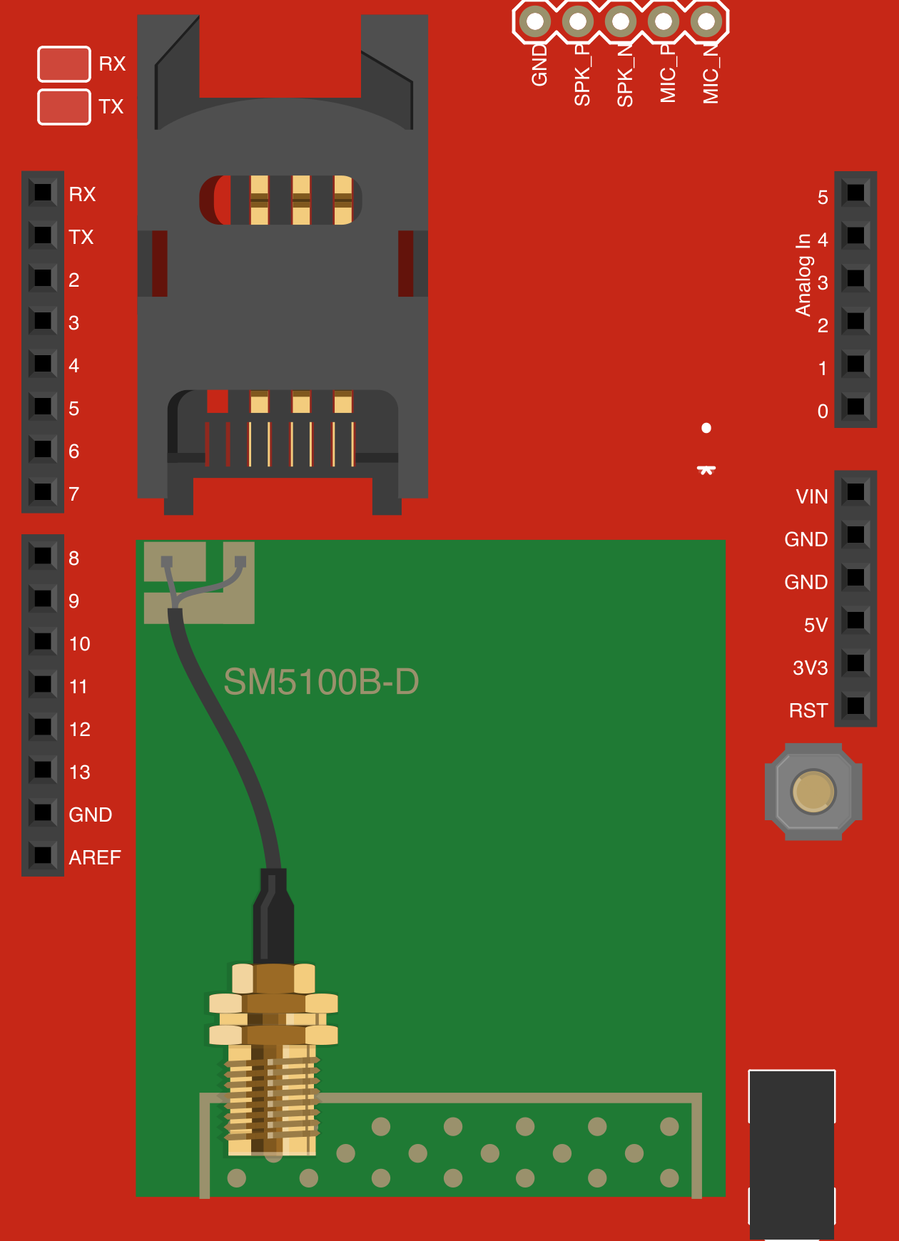
The Arduino Cellular Shield by SparkFun Electronics is a hardware module designed to enable Arduino boards to connect to cellular networks. This shield facilitates data transmission and communication over cellular networks, making it an essential component for Internet of Things (IoT) applications. It supports GSM and GPRS protocols, allowing devices to send and receive data, SMS, and even make voice calls in some configurations.
Explore Projects Built with Arduino Cellular Shield
 Open Project in Cirkit Designer
 Open Project in Cirkit Designer
 Open Project in Cirkit Designer
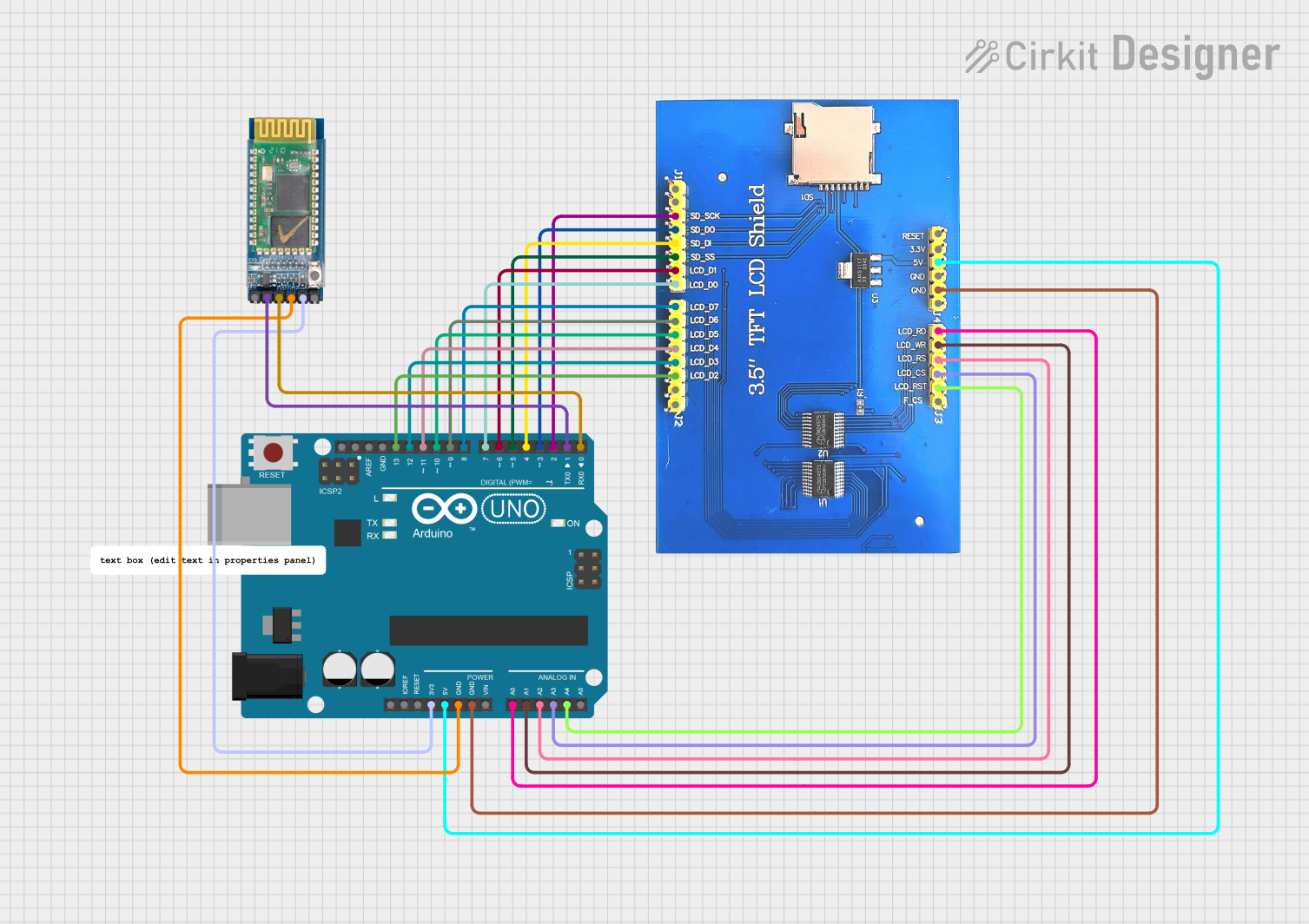 Open Project in Cirkit Designer
Explore Projects Built with Arduino Cellular Shield
Open Project in Cirkit DesignerOpen Project in Cirkit DesignerOpen Project in Cirkit DesignerOpen Project in Cirkit DesignerCommon Applications and Use Cases
- Remote monitoring and control of IoT devices
- GPS tracking and fleet management
- Environmental data collection in remote areas
- SMS-based alert systems
- Smart agriculture and industrial automation
Technical Specifications
The Arduino Cellular Shield is built to integrate seamlessly with Arduino boards, providing reliable cellular connectivity. Below are the key technical details:
General Specifications
| Parameter | Value |
|---|---|
| Cellular Module | Quectel M10 GSM/GPRS module |
| Frequency Bands | Quad-band: 850/900/1800/1900 MHz |
| Data Protocols | GSM, GPRS (Class 10) |
| Power Supply Voltage | 5V (via Arduino) |
| Power Consumption | Idle: ~10mA, Active: ~250mA |
| SIM Card Slot | Standard SIM card (2FF size) |
| Antenna Connector | U.FL connector for external antenna |
| Operating Temperature | -40°C to +85°C |
Pin Configuration and Descriptions
The Arduino Cellular Shield connects to the Arduino board via its standard headers. Below is the pin configuration:
| Pin Name | Description |
|---|---|
| D2 (RX) | Serial communication receive pin (connected to the GSM module TX pin) |
| D3 (TX) | Serial communication transmit pin (connected to the GSM module RX pin) |
| D7 | Power control pin for the GSM module |
| D9 | Status indicator pin (HIGH when the GSM module is powered on) |
| GND | Ground connection |
| 5V | Power supply input (from Arduino board) |
Usage Instructions
How to Use the Arduino Cellular Shield in a Circuit
Hardware Setup:
- Attach the Arduino Cellular Shield to your Arduino board by aligning the headers.
- Insert a standard SIM card (2FF size) into the SIM card slot on the shield.
- Connect an external antenna to the U.FL connector for better signal reception.
- Power the Arduino board via USB or an external power source.
Software Setup:
- Install the required libraries for GSM communication, such as the
GSMlibrary in the Arduino IDE. - Configure the library with your SIM card's APN (Access Point Name) for GPRS data.
- Install the required libraries for GSM communication, such as the
Basic Circuit Example:
- Connect the shield to the Arduino board.
- Ensure the antenna is securely connected.
- Use the following example code to send an SMS:
#include <GSM.h>

// Initialize GSM library
GSM gsmAccess; // Handles GSM connection
GSM_SMS sms;   // Handles SMS functionality

void setup() {
  Serial.begin(9600);
  while (!Serial) {
    // Wait for the serial port to connect
  }
  Serial.println("Initializing GSM module...");

  // Connect to the GSM network
  bool connected = false;
  while (!connected) {
    if (gsmAccess.begin() == GSM_READY) {
      connected = true;
      Serial.println("GSM module connected!");
    } else {
      Serial.println("Failed to connect. Retrying...");
      delay(1000);
    }
  }

  // Send an SMS
  Serial.println("Sending SMS...");
  sms.beginSMS("+1234567890"); // Replace with recipient's phone number
  sms.print("Hello from Arduino Cellular Shield!");
  sms.endSMS();
  Serial.println("SMS sent successfully!");
}

void loop() {
  // No actions in the loop
}
Important Considerations and Best Practices
- Ensure the SIM card is active and has sufficient balance for SMS or data usage.
- Use an external power source if the Arduino board cannot supply sufficient current.
- Place the antenna in an open area for better signal reception.
- Avoid using the shield in areas with poor cellular coverage to prevent connection issues.
Troubleshooting and FAQs
Common Issues and Solutions
Issue: GSM module fails to connect to the network.
- Solution: Verify the SIM card is inserted correctly and is active. Check the APN settings in the code.
Issue: SMS not being sent.
- Solution: Ensure the recipient's phone number is correct and includes the country code. Check for sufficient balance on the SIM card.
Issue: Poor signal reception.
- Solution: Reposition the antenna to an open area or use a higher-gain antenna.
Issue: Arduino board resets when the GSM module is active.
- Solution: Use an external power source to provide sufficient current to the shield.
FAQs
Q: Can I use this shield with an Arduino Mega?
- A: Yes, but you may need to modify the software serial pins in the code.
Q: Does the shield support 3G or 4G networks?
- A: No, the shield only supports GSM and GPRS (2G) networks.
Q: Can I use this shield for voice calls?
- A: Yes, the shield supports voice calls, but additional configuration is required.
Q: How do I update the firmware on the GSM module?
- A: Firmware updates are not typically required. Contact SparkFun support for assistance if needed.