How to Use ESP32-C6 Super Mini: Examples, Pinouts, and Specs
Introduction
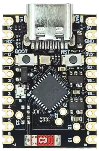
The ESP32-C6 Super Mini is a compact and powerful microcontroller designed for IoT applications and embedded systems. It features integrated Wi-Fi 6, Bluetooth 5.0, and IEEE 802.15.4 (Thread/Zigbee) capabilities, making it a versatile choice for modern wireless communication needs. Its small form factor and energy-efficient design make it ideal for battery-powered devices, smart home systems, wearables, and industrial automation.
Explore Projects Built with ESP32-C6 Super Mini


Explore Projects Built with ESP32-C6 Super Mini
Common Applications
- Smart home devices (e.g., smart plugs, thermostats, and lighting systems)
- IoT sensors and gateways
- Wearable technology
- Industrial automation and monitoring
- Wireless communication hubs (Wi-Fi, Bluetooth, Zigbee)
Technical Specifications
The following table outlines the key technical details of the ESP32-C6 Super Mini:
| Specification | Details |
|---|---|
| Microcontroller Core | 32-bit RISC-V single-core processor |
| Clock Speed | Up to 160 MHz |
| Flash Memory | 4 MB (external SPI flash) |
| RAM | 512 KB SRAM |
| Wireless Connectivity | Wi-Fi 6 (802.11ax), Bluetooth 5.0, IEEE 802.15.4 (Thread/Zigbee) |
| Operating Voltage | 3.3V |
| GPIO Pins | 22 GPIO pins (multiplexed with other functions) |
| Communication Interfaces | UART, SPI, I2C, I2S, PWM, ADC, DAC |
| ADC Resolution | 12-bit |
| Power Consumption | Ultra-low power modes available |
| Dimensions | 18 mm x 25 mm |
Pin Configuration and Descriptions
The ESP32-C6 Super Mini has a total of 22 GPIO pins, which are multifunctional. Below is the pinout description:
| Pin | Name | Function |
|---|---|---|
| 1 | GND | Ground |
| 2 | 3V3 | 3.3V power input |
| 3 | EN | Enable pin (active high) |
| 4 | GPIO0 | General-purpose I/O, boot mode selection |
| 5 | GPIO1 | General-purpose I/O, UART TX |
| 6 | GPIO2 | General-purpose I/O, ADC input |
| 7 | GPIO3 | General-purpose I/O, UART RX |
| 8 | GPIO4 | General-purpose I/O, PWM output |
| 9 | GPIO5 | General-purpose I/O, SPI CLK |
| 10 | GPIO6 | General-purpose I/O, SPI MOSI |
| 11 | GPIO7 | General-purpose I/O, SPI MISO |
| 12 | GPIO8 | General-purpose I/O, I2C SDA |
| 13 | GPIO9 | General-purpose I/O, I2C SCL |
| 14 | GPIO10 | General-purpose I/O, ADC input |
| 15 | GPIO11 | General-purpose I/O, DAC output |
| 16 | GPIO12 | General-purpose I/O, PWM output |
| 17 | GPIO13 | General-purpose I/O, ADC input |
| 18 | GPIO14 | General-purpose I/O, UART TX |
| 19 | GPIO15 | General-purpose I/O, UART RX |
| 20 | GPIO16 | General-purpose I/O, ADC input |
| 21 | GPIO17 | General-purpose I/O, DAC output |
| 22 | RST | Reset pin (active low) |
Usage Instructions
How to Use the ESP32-C6 Super Mini in a Circuit
- Power Supply: Provide a stable 3.3V power supply to the 3V3 pin. Connect the GND pin to the ground of your circuit.
- Boot Mode: To upload code, connect GPIO0 to GND during power-up or reset. Disconnect GPIO0 from GND after uploading.
- Programming: Use a USB-to-UART adapter to connect the ESP32-C6 Super Mini to your computer. Connect the adapter's TX to GPIO3 (RX) and RX to GPIO1 (TX).
- Peripherals: Connect sensors, actuators, or other peripherals to the GPIO pins. Use the appropriate communication protocol (e.g., I2C, SPI, UART).
Important Considerations
- Voltage Levels: Ensure all connected peripherals operate at 3.3V logic levels to avoid damaging the ESP32-C6.
- Antenna Placement: For optimal wireless performance, avoid placing metal objects near the onboard antenna.
- Power Consumption: Use the ultra-low power modes for battery-powered applications to extend battery life.
Example: Connecting to an Arduino UNO
The ESP32-C6 Super Mini can communicate with an Arduino UNO via UART. Below is an example of how to send data from the Arduino to the ESP32-C6:
Arduino Code
void setup() {
  Serial.begin(9600); // Initialize UART communication at 9600 baud
}

void loop() {
  Serial.println("Hello from Arduino!"); // Send data to ESP32-C6
  delay(1000); // Wait for 1 second
}
ESP32-C6 Code
void setup() {
  Serial.begin(9600); // Initialize UART communication at 9600 baud
  Serial.println("ESP32-C6 Ready!"); // Confirm ESP32-C6 is running
}

void loop() {
  if (Serial.available() > 0) { // Check if data is available
    String data = Serial.readString(); // Read incoming data
    Serial.print("Received: "); // Print received data
    Serial.println(data);
  }
}
Troubleshooting and FAQs
Common Issues
- ESP32-C6 Not Responding
- Solution: Ensure the EN pin is connected to 3.3V. Check the power supply for stability.
- Code Upload Fails
- Solution: Verify that GPIO0 is connected to GND during boot. Check the USB-to-UART adapter connections.
- Wi-Fi or Bluetooth Not Working
- Solution: Ensure the onboard antenna is not obstructed. Check the firmware for proper configuration.
FAQs
- Can I power the ESP32-C6 with 5V?
- No, the ESP32-C6 operates at 3.3V. Use a voltage regulator if your power source is 5V.
- How do I reset the ESP32-C6?
- Pull the RST pin low momentarily to reset the microcontroller.
- What is the maximum range of Wi-Fi and Bluetooth?
- Wi-Fi range is approximately 50 meters indoors, while Bluetooth range is around 10 meters, depending on environmental factors.
This concludes the documentation for the ESP32-C6 Super Mini. For further assistance, refer to the official datasheet or community forums.