How to Use logo-rnaenor v2.0: Examples, Pinouts, and Specs
Introduction
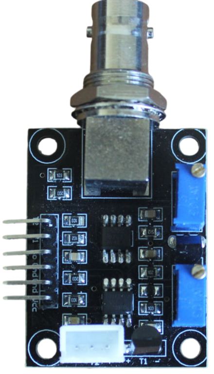
The Logo-RNAENOR V2.0 is a specialized circuit board designed for RNA sequencing applications. It features advanced signal processing capabilities and is optimized for high-throughput data acquisition. This component is tailored for use in bioinformatics and genomics research, where precise and efficient RNA sequencing is critical. Its robust design ensures reliable performance in demanding laboratory environments.
Explore Projects Built with logo-rnaenor v2.0

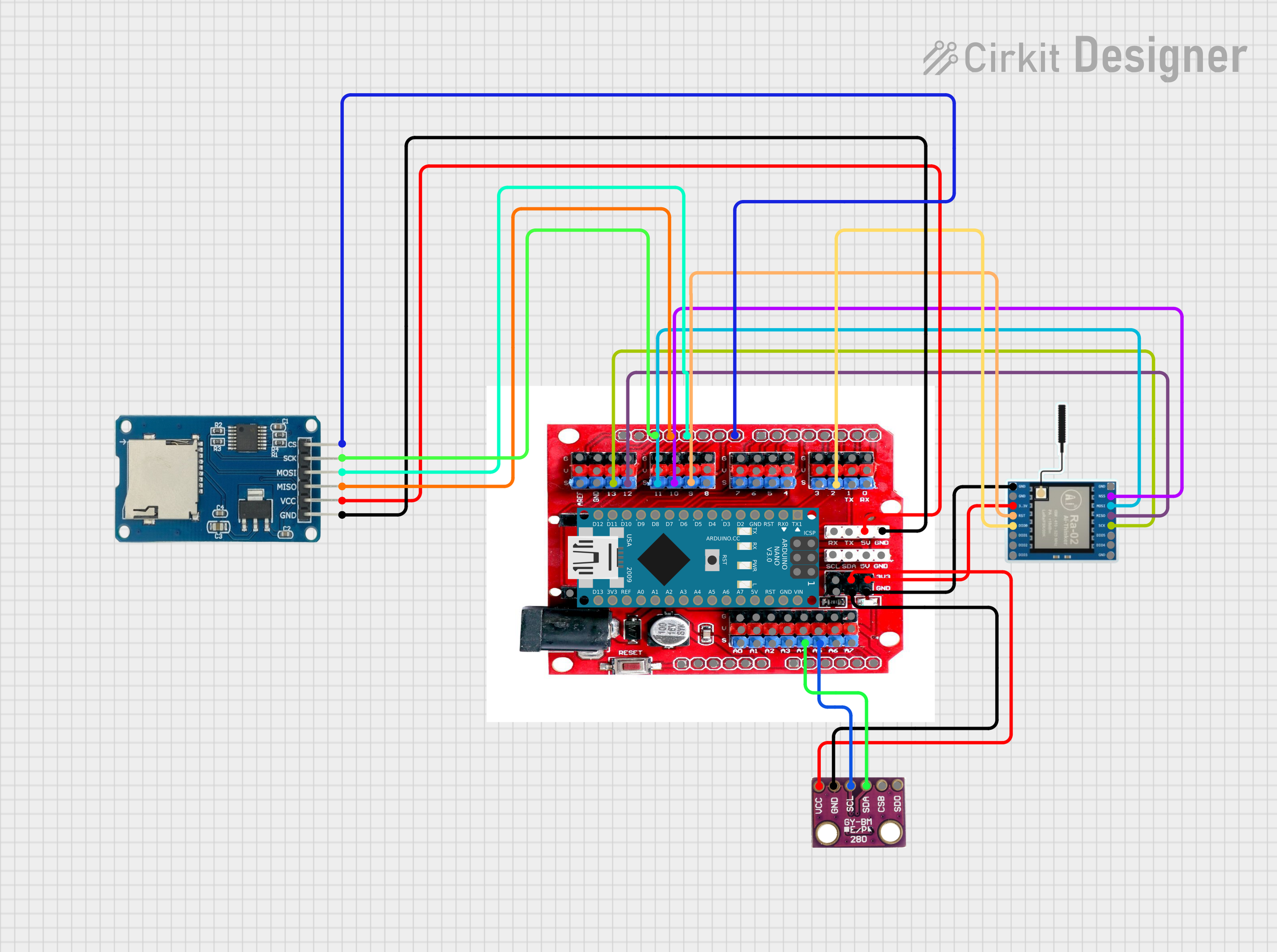
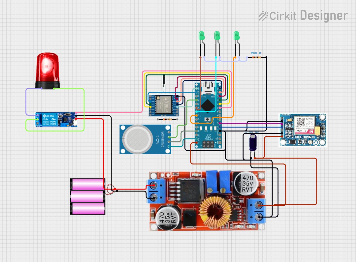
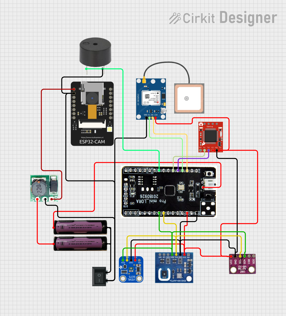
Explore Projects Built with logo-rnaenor v2.0
Common Applications and Use Cases
- RNA sequencing in genomics research
- High-throughput data acquisition for bioinformatics
- Signal processing in molecular biology experiments
- Integration into laboratory automation systems
- Educational tools for teaching RNA sequencing techniques
Technical Specifications
Key Technical Details
| Parameter | Specification |
|---|---|
| Operating Voltage | 3.3V - 5V |
| Power Consumption | 1.2W (typical) |
| Data Transfer Interface | USB 3.0, SPI |
| Signal Processing Speed | Up to 1 Gbps |
| Input Channels | 16 analog input channels |
| Output Channels | 4 digital output channels |
| Sampling Rate | 500 kHz per channel |
| Dimensions | 100mm x 80mm x 15mm |
| Operating Temperature | 0°C to 50°C |
| Storage Temperature | -20°C to 70°C |
Pin Configuration and Descriptions
| Pin Number | Pin Name | Description |
|---|---|---|
| 1 | VCC | Power supply input (3.3V - 5V) |
| 2 | GND | Ground connection |
| 3 | CH1_IN | Analog input channel 1 |
| 4 | CH2_IN | Analog input channel 2 |
| 5 | CH3_IN | Analog input channel 3 |
| 6 | CH4_IN | Analog input channel 4 |
| 7 | CH5_IN | Analog input channel 5 |
| 8 | CH6_IN | Analog input channel 6 |
| 9 | CH7_IN | Analog input channel 7 |
| 10 | CH8_IN | Analog input channel 8 |
| 11 | CH9_IN | Analog input channel 9 |
| 12 | CH10_IN | Analog input channel 10 |
| 13 | CH11_IN | Analog input channel 11 |
| 14 | CH12_IN | Analog input channel 12 |
| 15 | CH13_IN | Analog input channel 13 |
| 16 | CH14_IN | Analog input channel 14 |
| 17 | CH15_IN | Analog input channel 15 |
| 18 | CH16_IN | Analog input channel 16 |
| 19 | SPI_MOSI | SPI Master Out Slave In |
| 20 | SPI_MISO | SPI Master In Slave Out |
| 21 | SPI_CLK | SPI Clock |
| 22 | SPI_CS | SPI Chip Select |
| 23 | USB_D+ | USB Data Positive |
| 24 | USB_D- | USB Data Negative |
| 25 | RESET | Reset pin |
| 26 | STATUS_LED | Status indicator LED output |
Usage Instructions
How to Use the Component in a Circuit
- Power Supply: Connect the VCC pin to a 3.3V or 5V power source and the GND pin to ground.
- Input Connections: Attach the analog signals to the appropriate input channels (CH1_IN to CH16_IN).
- Data Transfer: Use the USB 3.0 interface for high-speed data transfer or the SPI interface for custom integration.
- Output Connections: Connect the digital output channels to external devices if needed.
- Status Monitoring: Use the STATUS_LED pin to monitor the operational status of the board.
Important Considerations and Best Practices
- Ensure the power supply voltage is within the specified range to avoid damage.
- Use shielded cables for analog inputs to minimize noise and interference.
- For high-speed data transfer, prefer the USB 3.0 interface over SPI.
- Keep the board in a temperature-controlled environment to maintain optimal performance.
- Regularly update the firmware to access the latest features and improvements.
Example: Connecting to an Arduino UNO
The Logo-RNAENOR V2.0 can be interfaced with an Arduino UNO for basic control and data acquisition. Below is an example code snippet:
#include <SPI.h>

// Define SPI pins for Arduino
const int chipSelectPin = 10; // Chip Select pin for SPI communication

void setup() {
  // Initialize serial communication for debugging
  Serial.begin(9600);

  // Initialize SPI communication
  pinMode(chipSelectPin, OUTPUT);
  digitalWrite(chipSelectPin, HIGH); // Set CS pin high
  SPI.begin();

  Serial.println("Logo-RNAENOR V2.0 initialized.");
}

void loop() {
  // Example: Send a command to the Logo-RNAENOR V2.0
  digitalWrite(chipSelectPin, LOW); // Select the device
  SPI.transfer(0x01); // Send a sample command (e.g., start data acquisition)
  digitalWrite(chipSelectPin, HIGH); // Deselect the device

  // Add a delay for demonstration purposes
  delay(1000);

  // Example: Read data from the device
  digitalWrite(chipSelectPin, LOW); // Select the device
  byte response = SPI.transfer(0x00); // Send dummy byte to receive data
  digitalWrite(chipSelectPin, HIGH); // Deselect the device

  // Print the received data
  Serial.print("Received data: ");
  Serial.println(response, HEX);

  delay(1000); // Wait before the next loop iteration
}
Troubleshooting and FAQs
Common Issues Users Might Face
No Power or LED Indicator Not Lit:
- Ensure the VCC and GND pins are properly connected.
- Verify the power supply voltage is within the 3.3V - 5V range.
Data Transfer Issues:
- Check the USB or SPI connections for loose or incorrect wiring.
- Ensure the correct drivers are installed for USB communication.
Noise in Analog Signals:
- Use shielded cables for input connections.
- Place the board away from high-frequency noise sources.
Overheating:
- Ensure the board is operated within the specified temperature range.
- Avoid placing the board in direct sunlight or near heat sources.
Solutions and Tips for Troubleshooting
- Firmware Update: Regularly check for firmware updates from the manufacturer to resolve known issues.
- Debugging: Use the STATUS_LED pin to monitor the board's operational status.
- Testing: Test the board with a simple setup before integrating it into a complex system.
- Documentation: Refer to the official datasheet for detailed technical information.
By following this documentation, users can effectively utilize the Logo-RNAENOR V2.0 for their RNA sequencing and data acquisition needs.