How to Use ESP32-S3 SUPERMINI: Examples, Pinouts, and Specs
Introduction
The ESP32-S3 SUPERMINI is a compact and powerful microcontroller module designed for IoT applications and embedded systems. It features dual-core processing, integrated Wi-Fi, and Bluetooth Low Energy (BLE) capabilities, making it an excellent choice for projects requiring wireless connectivity and efficient performance. Its small form factor and robust processing power make it ideal for applications such as smart home devices, wearable electronics, industrial automation, and more.
Explore Projects Built with ESP32-S3 SUPERMINI


Explore Projects Built with ESP32-S3 SUPERMINI
Common Applications
- IoT devices and smart home systems
- Wearable technology
- Wireless sensor networks
- Industrial automation and control
- Robotics and drones
- Edge computing and AI/ML applications
Technical Specifications
The following table outlines the key technical specifications of the ESP32-S3 SUPERMINI:
| Specification | Details |
|---|---|
| Processor | Dual-core Xtensa® LX7, up to 240 MHz |
| Wireless Connectivity | Wi-Fi 802.11 b/g/n (2.4 GHz), Bluetooth 5.0 LE |
| Flash Memory | 8 MB (varies by model) |
| RAM | 512 KB SRAM + 2 MB PSRAM |
| GPIO Pins | Up to 45 GPIOs (multiplexed with other functions) |
| Operating Voltage | 3.3V |
| Power Consumption | Ultra-low power modes available |
| Interfaces | SPI, I2C, I2S, UART, PWM, ADC, DAC, USB OTG |
| Dimensions | 16 mm x 23 mm |
| Security Features | Hardware encryption, secure boot, flash encryption |
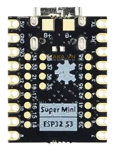
Pin Configuration
The ESP32-S3 SUPERMINI has a variety of pins for different functionalities. Below is a summary of the pin configuration:
| Pin Name | Function | Description |
|---|---|---|
| GND | Ground | Connect to the ground of the circuit. |
| 3V3 | Power Input | 3.3V power supply input. |
| EN | Enable | Active-high enable pin to reset or wake the module. |
| GPIO0 | Boot Mode/General Purpose I/O | Used for boot mode selection or as a general-purpose pin. |
| GPIO1-45 | General Purpose I/O | Configurable for digital I/O, ADC, DAC, PWM, etc. |
| TXD0/RXD0 | UART0 TX/RX | Default UART for serial communication. |
| USB D+ / D- | USB Data Lines | USB OTG interface for programming or data transfer. |
Note: Pin functionality may vary depending on the firmware configuration. Refer to the datasheet for detailed pin multiplexing options.
Usage Instructions
How to Use the ESP32-S3 SUPERMINI in a Circuit
- Power Supply: Provide a stable 3.3V power supply to the
3V3pin and connectGNDto the ground of your circuit. - Programming: Use the USB interface or UART pins (TXD0/RXD0) to upload firmware. The module supports the Arduino IDE, ESP-IDF, and other development environments.
- GPIO Configuration: Configure GPIO pins as input, output, or alternate functions (e.g., ADC, PWM) in your code.
- Wi-Fi and Bluetooth: Use the built-in libraries (e.g.,
WiFi.horBLEDevice.h) to enable wireless communication.
Example: Connecting to Wi-Fi with Arduino IDE
Below is an example of how to connect the ESP32-S3 SUPERMINI to a Wi-Fi network using the Arduino IDE:
#include <WiFi.h> // Include the Wi-Fi library

// Replace with your network credentials
const char* ssid = "Your_SSID";       // Your Wi-Fi network name
const char* password = "Your_Password"; // Your Wi-Fi network password

void setup() {
  Serial.begin(115200); // Initialize serial communication
  delay(1000);          // Wait for the serial monitor to initialize

  Serial.println("Connecting to Wi-Fi...");
  WiFi.begin(ssid, password); // Start Wi-Fi connection

  // Wait until the module connects to the Wi-Fi network
  while (WiFi.status() != WL_CONNECTED) {
    delay(500);
    Serial.print(".");
  }

  Serial.println("\nWi-Fi connected!");
  Serial.print("IP Address: ");
  Serial.println(WiFi.localIP()); // Print the assigned IP address
}

void loop() {
  // Add your main code here
}
Important Considerations
- Power Supply: Ensure a stable 3.3V power source to avoid instability.
- GPIO Voltage Levels: The GPIO pins are not 5V tolerant. Use level shifters if interfacing with 5V devices.
- Antenna Placement: Avoid placing metal objects near the module's antenna to ensure optimal wireless performance.
- Firmware Updates: Keep the firmware updated to benefit from the latest features and security patches.
Troubleshooting and FAQs
Common Issues and Solutions
Module Not Responding
- Cause: Incorrect power supply or wiring.
- Solution: Verify the power supply is 3.3V and check all connections.
Wi-Fi Connection Fails
- Cause: Incorrect SSID or password.
- Solution: Double-check the network credentials in your code.
Serial Monitor Shows Garbage Data
- Cause: Incorrect baud rate.
- Solution: Ensure the baud rate in the serial monitor matches the
Serial.begin()value in your code.
GPIO Pin Not Working
- Cause: Pin conflict or incorrect configuration.
- Solution: Check the pin's alternate functions and ensure it is not being used by another peripheral.
FAQs
Q: Can the ESP32-S3 SUPERMINI be powered via USB?
A: Yes, the module can be powered via the USB interface for programming and testing.Q: Does the module support over-the-air (OTA) updates?
A: Yes, the ESP32-S3 SUPERMINI supports OTA updates for firmware.Q: What development environments are compatible with this module?
A: The module is compatible with the Arduino IDE, ESP-IDF, PlatformIO, and other environments.Q: Can I use the ESP32-S3 SUPERMINI for battery-powered applications?
A: Yes, the module supports ultra-low power modes, making it suitable for battery-powered projects.
By following this documentation, you can effectively integrate the ESP32-S3 SUPERMINI into your projects and troubleshoot common issues. For advanced configurations, refer to the official datasheet and technical resources.