How to Use step up boost converter: Examples, Pinouts, and Specs
Introduction
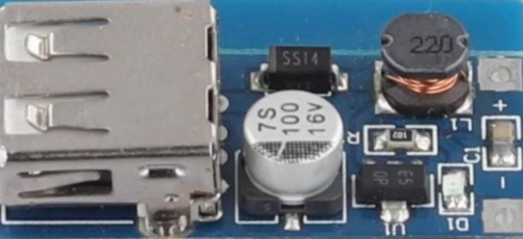
A step-up boost converter is a type of DC-DC converter designed to increase the input voltage to a higher output voltage while maintaining power. It achieves this by utilizing an inductor, a switch (typically a transistor), a diode, and a capacitor to store and transfer energy efficiently. This component is widely used in applications where a higher voltage is required from a lower voltage source.
Explore Projects Built with step up boost converter


Explore Projects Built with step up boost converter
Common Applications and Use Cases
- Powering devices requiring higher voltage from batteries (e.g., 3.7V to 12V)
- Solar-powered systems to step up low panel voltages
- LED drivers for high-power LEDs
- USB power banks
- Portable electronics and embedded systems
Technical Specifications
Below are the general technical specifications for a typical step-up boost converter. Note that specific values may vary depending on the manufacturer and model.
| Parameter | Value |
|---|---|
| Input Voltage Range | 2V to 24V (varies by model) |
| Output Voltage Range | 5V to 50V (adjustable in some models) |
| Output Current | Up to 2A (varies by model) |
| Efficiency | Up to 95% |
| Switching Frequency | 100 kHz to 1 MHz |
| Operating Temperature | -40°C to +85°C |
Pin Configuration and Descriptions
The pinout of a step-up boost converter module may vary depending on the design, but a common configuration is as follows:
| Pin Name | Description |
|---|---|
| VIN | Positive input voltage terminal |
| GND | Ground terminal for input and output |
| VOUT | Positive output voltage terminal |
| EN (optional) | Enable pin to turn the converter on/off (active high) |
Usage Instructions
How to Use the Component in a Circuit
Connect the Input Voltage (VIN):
- Attach the positive terminal of your power source (e.g., battery) to the VIN pin.
- Connect the negative terminal of your power source to the GND pin.
Connect the Output Load:
- Attach the positive terminal of your load (e.g., LED, motor) to the VOUT pin.
- Connect the negative terminal of your load to the GND pin.
Adjust the Output Voltage (if adjustable):
- Some boost converters have a potentiometer to adjust the output voltage.
- Use a multimeter to measure the output voltage while turning the potentiometer until the desired voltage is achieved.
Enable the Converter (if applicable):
- If the module has an EN (enable) pin, ensure it is connected to a HIGH signal (e.g., 3.3V or 5V) to activate the converter.
Important Considerations and Best Practices
- Input Voltage Range: Ensure the input voltage is within the specified range of the converter to avoid damage.
- Output Voltage Setting: If the converter is adjustable, set the output voltage before connecting the load to prevent overvoltage damage.
- Heat Dissipation: For high-power applications, ensure proper heat dissipation using heatsinks or active cooling if necessary.
- Capacitor Selection: Use low-ESR capacitors for input and output filtering to improve stability and reduce noise.
- Load Current: Do not exceed the maximum output current rating to avoid overheating or failure.
Example: Using a Step-Up Boost Converter with Arduino UNO
Below is an example of using a step-up boost converter to power a 12V LED strip from a 5V Arduino UNO power source.
Circuit Connections
- Connect the Arduino's 5V pin to the VIN pin of the boost converter.
- Connect the Arduino's GND pin to the GND pin of the boost converter.
- Adjust the boost converter's output to 12V using the potentiometer.
- Connect the VOUT pin of the boost converter to the positive terminal of the LED strip.
- Connect the GND pin of the boost converter to the negative terminal of the LED strip.
Arduino Code Example
// This code demonstrates controlling the LED strip using a PWM signal
// from the Arduino UNO. The boost converter steps up the voltage to 12V.

const int pwmPin = 9; // PWM pin connected to the LED strip

void setup() {
  pinMode(pwmPin, OUTPUT); // Set the PWM pin as an output
}

void loop() {
  // Gradually increase brightness
  for (int brightness = 0; brightness <= 255; brightness++) {
    analogWrite(pwmPin, brightness); // Write PWM signal to control brightness
    delay(10); // Small delay for smooth transition
  }

  // Gradually decrease brightness
  for (int brightness = 255; brightness >= 0; brightness--) {
    analogWrite(pwmPin, brightness); // Write PWM signal to control brightness
    delay(10); // Small delay for smooth transition
  }
}
Troubleshooting and FAQs
Common Issues and Solutions
No Output Voltage:
- Cause: Input voltage is too low or not connected properly.
- Solution: Verify the input voltage is within the specified range and check connections.
Output Voltage is Incorrect:
- Cause: Potentiometer is not adjusted correctly.
- Solution: Use a multimeter to measure and adjust the output voltage.
Overheating:
- Cause: Exceeding the maximum current rating or poor heat dissipation.
- Solution: Reduce the load current or add a heatsink to the converter.
High Noise or Instability:
- Cause: Poor input/output filtering or unsuitable capacitors.
- Solution: Use low-ESR capacitors and ensure proper grounding.
FAQs
Q: Can I use a step-up boost converter to power sensitive electronics?
A: Yes, but ensure the output voltage is stable and within the tolerance range of your device. Adding additional filtering capacitors can help reduce noise.
Q: What happens if I reverse the input polarity?
A: Most boost converters do not have reverse polarity protection and may be damaged. Always double-check connections before powering the circuit.
Q: Can I use the boost converter with a solar panel?
A: Yes, but ensure the input voltage from the solar panel is within the converter's range, and consider using a capacitor to stabilize the input.
Q: How do I calculate the efficiency of the boost converter?
A: Efficiency (%) = (Output Power / Input Power) × 100. Measure the input and output voltage and current to calculate power.
This concludes the documentation for the step-up boost converter.